Detector for radiation, particularly high energy electromagnetic radiation

a high-energy electromagnetic radiation and detector anode technology, applied in the field of radiation detectors, can solve the problems of not all electrons of the electron avalanche can be detected by the detector anode, the spatial resolution of the detector is relatively low, and the bulkyness of the detector, etc., to achieve the effect of precise measurements

Inactive Publication Date: 2017-03-14
SIEMENS AG
View PDF19 Cites 0 Cited by
  • Summary
  • Abstract
  • Description
  • Claims
  • Application Information

AI Technical Summary

Benefits of technology

[0009]Embodiments of the detector anode extends at each hole from the second electrode over the hole such that the hole is covered at one side completely by the detector anode. Based on the realization that by covering the holes of a gas electron multiplier by the detector anode, no electrons of the electron avalanche are lost due to discharge at the second electrode. Hence, a more precise measurement of the radiation can be achieved by this detector. Furthermore, embodiments of the detector have a much more compact size in comparison to scintillation detectors with photomultiplier tubes because the thickness of gas electron multipliers usually lies in the range of several microns compared to several centimeters for a photomultiplier. Moreover, the spatial resolution of a gas electron multiplier can be made much higher in comparison to scintillation detectors including photomultiplier tubes.
[0010]In a preferred embodiment of the detector, the converting section comprises a photocathode and a scintillator material, e.g. Nal(Tl), disposed at the side of the photocathode facing the radiation entering the converting section. The scintillator material converts the incident radiation in light. The photons of this light cause electrons to be emitted directly from the photocathode due to the photoelectric effect. As a consequence, the photocathode can be arranged near the holes of the gas electron multiplier reducing the size of the detector. However, in another embodiment, the converting section may also comprise a conventional cathode and a gas volume such that the radiation goes through the cathode and causes the emission of electrons from the gas atoms / molecules in the gas volume due to the photoelectric effect.
[0012]In a particularly preferred embodiment of the invention, the detector anode and the second electrode form an integral electrode leading to a simple design of the detector.
[0014]In another embodiment, the detector anode has at one or more holes and particularly at each hole a U-shaped cross-section along a plane perpendicular to the second electrode. Furthermore, the detector anode may have at one or more holes and particularly at each hole a half-elliptic cross-section. Due to the use of a U-shaped or half-elliptic cross-section, the detector surface of the anode is increased.

Problems solved by technology

Scintillation detectors are relatively bulky due to the photomultiplier tube which has a length of several centimeters.
Furthermore, the spatial resolution of those detectors is relatively low.
The detector has the disadvantage that not all electrons of the electron avalanche can be detected by the detector anode because some electrons are discharged on the electrode of the gas electron multiplier adjacent to the detector anode.
However, also a gap filled with gas may be present between the photocathode and the first electrode.

Method used


Image

  • Detector for radiation, particularly high energy electromagnetic radiation
  • Detector for radiation, particularly high energy electromagnetic radiation
  • Detector for radiation, particularly high energy electromagnetic radiation

Examples


Embodiment Construction

[0024]In the following, embodiments of the invention will be described with respect to a scintillation detector including a plurality of cells for detecting high-energy electromagnetic radiation and particularly X-Ray radiation and / or Gamma radiation.

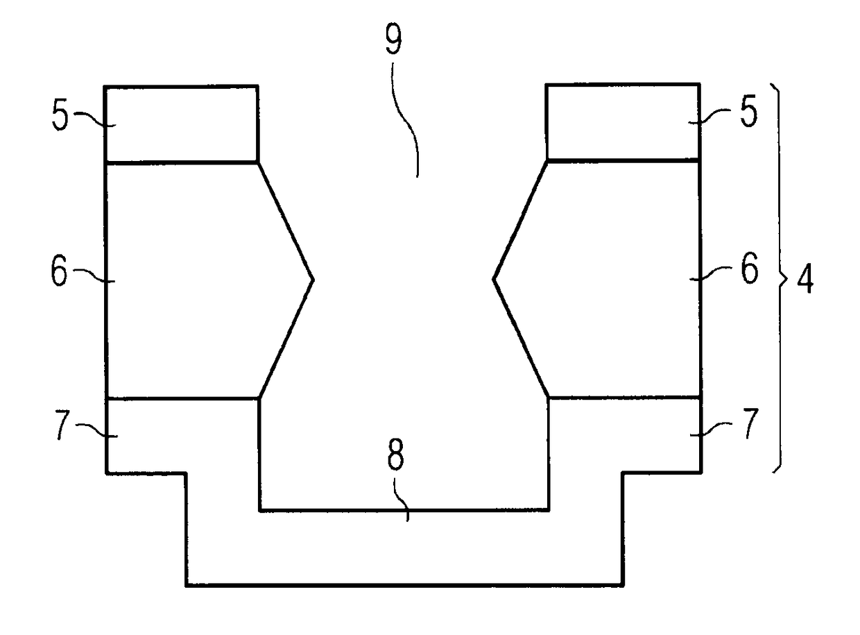
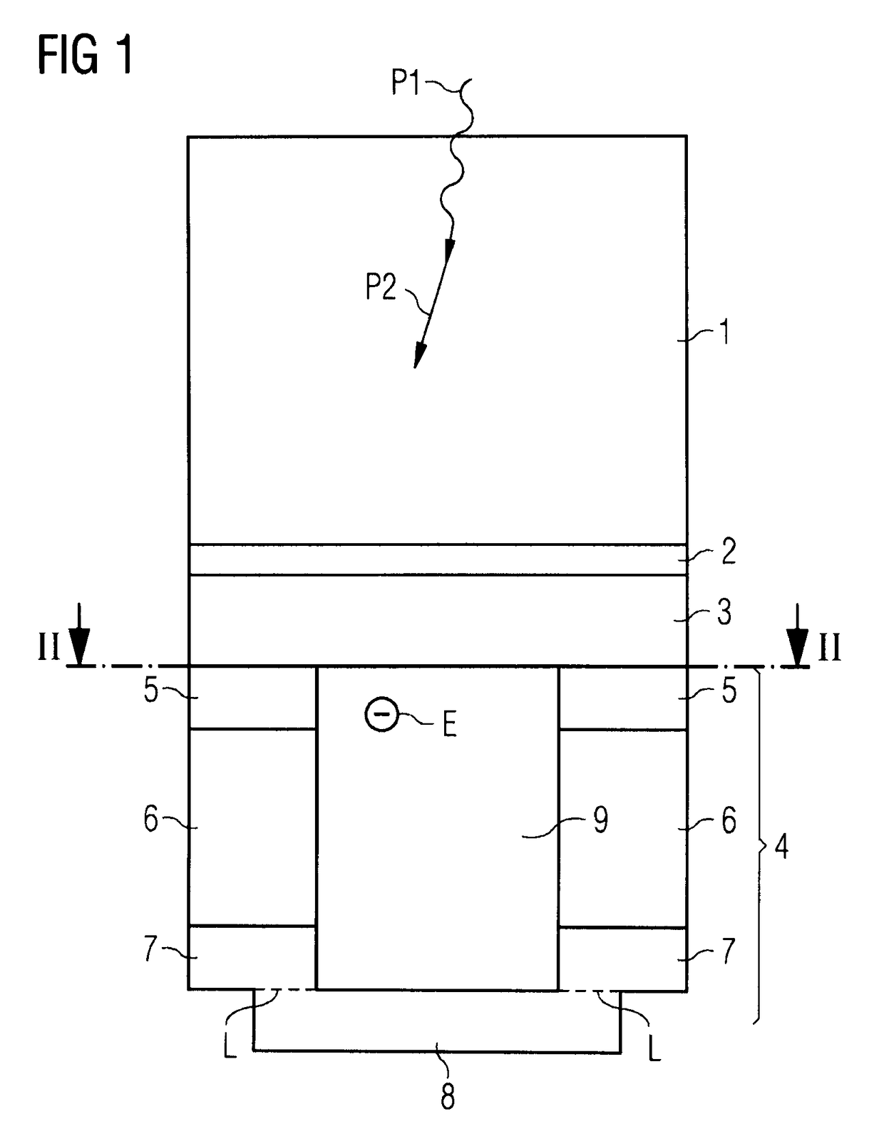
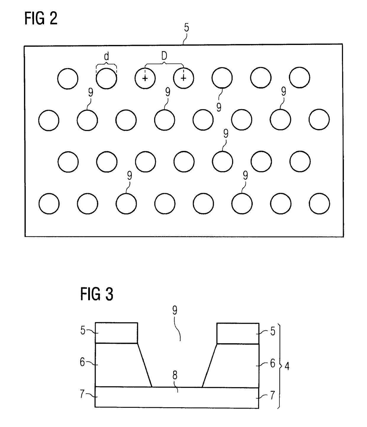
[0025]FIG. 1 shows a sectional view of one cell of a detector according to a first embodiment of the invention. The detector includes a scintillation material 1 which converts the high energy radiation to be detected (indicated by arrow P1) in light (indicated by arrow P2), i.e. in an electromagnetic radiation with another wavelength than the incident radiation. Depending on the scintillator material, the light produced in the material may lie within the visible spectrum or in a spectrum adjacent to the visible spectrum. In a preferred embodiment, NaI(Tl) (Sodium Iodide activated with Thallium) is used as a scintillator crystal. An optical transmissive window 2 (preferably made of an appropriate glass) is disposed at the bottom of this ...


PUM


Abstract

A detector for radiation, particularly high energy electromagnetic radiation is provided. The detector includes a converting section including a cathode for converting the radiation incident on the converting section in electrons by the photoelectric effect. The detector further includes a gas electron multiplier for generating an electron avalanche from electrons which are generated by the converting section and enter the gas electron multiplier, the gas electron multiplier including a first electrode, a dielectric layer and a second electrode, the first electrode being disposed at a first side of the dielectric layer adjacent to the converting section and the second electrode being disposed at a second side of the dielectric layer opposite to the first side. The gas electron multiplier includes a number of holes filled with gas, the holes extending through the first electrode, the dielectric layer and the second electrode.

Description

CROSS-REFERENCE TO RELATED APPLICATIONS[0001]This application claims priority to PCT Application No. PCT / RU2012 / 000450, having a filing date of Jun. 8, 2012, the entire contents of which are hereby incorporated by reference.FIELD OF TECHNOLOGY[0002]The following relates to a detector for radiation, particularly high energy electro-magnetic radiation.BACKGROUND[0003]For the detection of radiation, many different types of detectors are known from the prior art. For sensing high energy electromagnetic radiation, scintillation detectors comprising a scintillator crystal and a photomultiplier tube are widely used in different technical fields, e.g. in medical imaging equipment or for well-logging in the oil and gas industry. In a scintillation detector, the radiation falls on a scintillator crystal converting the radiation in light impinging on a photocathode. This photocathode is part of a photomultiplier tube comprising a plurality of dynodes in a glass envelope. Due to the photoelectr...

Claims


Application Information

Patent Timeline
Patent Type & Authority Patents(United States)
IPC IPC(8): G01V5/04G01T1/185H01J47/02G01T1/20
CPCG01T1/185G01T1/2006H01J47/02H01J47/024G01T1/20
Inventor ASTAFIEVA, IRINAHEID, OLIVERHUGHES, TIMOTHY
Owner SIEMENS AG
Why Eureka
Try Eureka