Caliper for disc brakes

a disc brake and caliper technology, applied in the direction of manufacturing tools, foundry patterns, foundry moulding apparatus, etc., can solve the problems of difficult processing, long time to start up the hole opening processing, and deterioration of yield, so as to improve the productivity and improve the effect of braking stability, position shift in the hole processing

Active Publication Date: 2017-03-21
NIPPON LIGHT METAL CO LTD
View PDF17 Cites 3 Cited by
  • Summary
  • Abstract
  • Description
  • Claims
  • Application Information

AI Technical Summary

Benefits of technology

[0025]With the disc brake caliper according to the present invention, the hydraulic cylinders of the inner caliper section and the outer caliper section can be linked by the cylinder-side hydraulic channels via the bridge section and the hydraulic linking channel that links those cylinder-side hydraulic channels can be molded integrally simultaneously with the cylinder-side hydraulic channels. As a result, it is unnecessary to perform processing for forming a hole with a drill after casting, i.e., to perform machining, to make the hydraulic linking channel for linking the cylinder-side hydraulic channels provided to the inner caliper section and the outer caliper section. Thus, the above-described effort made for the processing is lightened, thereby making it possible to improve the productivity greatly.
[0026]Further, since the cylinder-side hydraulic channels and the hydraulic linking channel are molded integrally with a core simultaneously at the time of casting, position shift in hole processing generated at the time of executing the hole processing can be avoided. As a result, the oil pressure works on each of the hydraulic cylinders of the inner caliper section and the outer caliper section uniformly at the time of using the caliper, so that stable braking can be expected and there is no issue of uneven wear and the like generated in the brake pads. As a result, the life of the brake pads can be extended.

Problems solved by technology

However, there are following issues with the existing technique described above.
Therefore, the processing is difficult and the processing precision may become poor, so that the yield is deteriorated as well.
Therefore, it takes a long time to start up the hole opening processing.
Thus, the processing time becomes long, thereby deteriorating the productivity.
As a result, the cost performance becomes poor.
However, it is not possible to judge whether or not those are linked in a 100% state.
Further, in a case where the oil pressure is not applied uniformly to the cylinders 105 of each of the caliper sections 102 and 103, braking becomes unstable and uneven wear and the like of the brake pads 107 occur, thereby producing an inferior piece.
Therefore, it takes a lot of effort and time, so that the cost performance in regards to those is poor as well.

Method used


Image

  • Caliper for disc brakes
  • Caliper for disc brakes
  • Caliper for disc brakes

Examples


Embodiment Construction

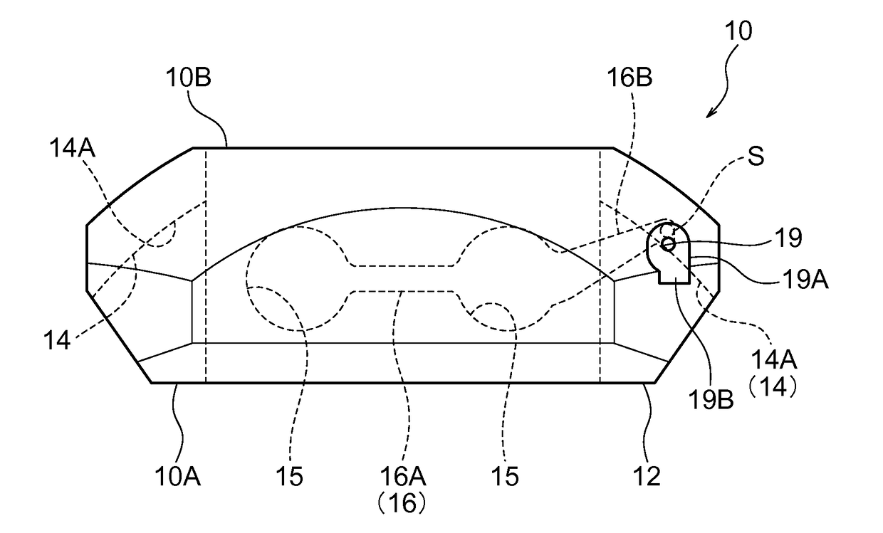
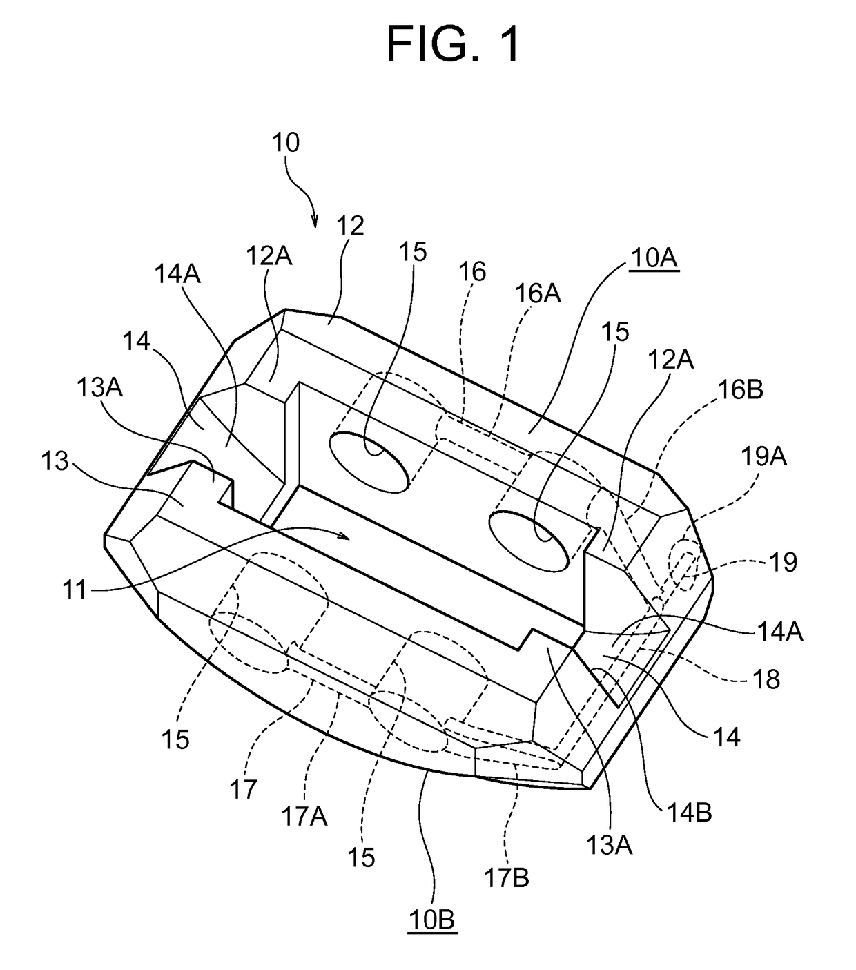
[0046]Hereinafter, an embodiment of a caliper for disc brakes according to the embodiment will be described in details by referring to FIGS. 1 to 16.

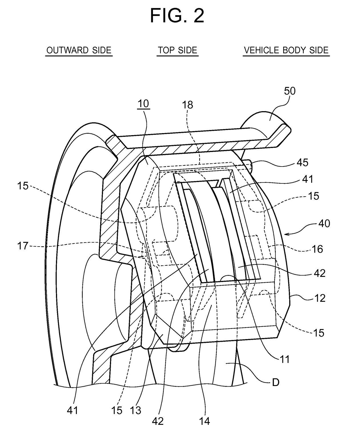
[0047]FIG. 1 shows the disc brake caliper (simply called a caliper hereinafter) 10 according to the embodiment, and FIG. 2 is an illustration showing a state where the caliper 10 is used as a disc brake 40 for automobiles.

[0048]First, the outlines of the disc brake 40 and the caliper 10 will be described by referring to FIGS. 1 and 2.

[0049]The caliper 10 is structured to include: an inner caliper section 12 and an outer caliper section 13 which are disposed to oppose to each other by having a disc rotor D interposed therebetween and the both end parts thereof in the length direction are linked integrally by a bridge section 14; and a plurality of hydraulic cylinders 15, 15 (two each on the inner caliper section 12 side and the outer caliper section 13 side in this embodiment) for pressurizing pistons which are provided in each of opposi...


PUM

PropertyMeasurementUnit
lengthaaaaaaaaaa
oil pressureaaaaaaaaaa
pressureaaaaaaaaaa

Abstract

A caliper comprises a hydraulic linking channel provided in a bridge section linking hydraulic cylinders, on an inner caliper section side, and hydraulic cylinders, on an outer caliper section side, to a cylinder-side hydraulic channel disposed on the back end of each respectively. A connecting channel forming section, which corresponds to each cylinder-side hydraulic channel and the hydraulic linking channel is provided, in advance, in a core used during casting of the inner caliper section, the outer caliper section, and the bridge section, and is formed by setting in a situation to be embedded at the same time as each caliper section and the bridge section are being integrally cast.

Description

TECHNICAL FIELD[0001]The present invention relates to a caliper for disc brakes. More specifically, the present invention relates to a disc brake caliper used for vehicles and the like, which brakes a disc rotor by moving forward pistons disposed by opposing to each other on both side faces of the disc rotor by oil pressure and having pads provided integrally at tip ends of the pistons pressed against the both side faces of the disc rotor.BACKGROUND ART[0002]In order to brake automobiles, disc brakes are used widely.[0003]The braking of automobiles by the disc brake is executed by pressing a pair of pads, which are disposed on the both sides in the axial direction of the disc rotor that rotates along with a wheel, against the both sides of the disc rotor by moving forward the piston inserted in a cylinder by oil pressure.[0004]In such disc brake, cylinders provided to an inner caliper section and an outer caliper section, respectively, are connected via an oil channel provided insid...

Claims


Application Information

Patent Timeline
Patent Type & Authority Patents(United States)
IPC IPC(8): F16D65/00F16D55/228F16D55/225F16D55/00F16D121/04F16D125/16
CPCF16D65/0068F16D55/225F16D55/228F16D2055/0016F16D2055/0091F16D2121/04F16D2125/16F16D65/092F16D65/14B22C9/108B22C9/22B22D25/02B22D29/001F16D55/22F16D2200/003F16D2250/0015
Inventor KAWAMATA, TAKAHIRONISHIMURA, TETSUZO
Owner NIPPON LIGHT METAL CO LTD
Why Eureka
Try Eureka