
Method and apparatus for multi-rate clock generation

a multi-rate clock and clock generation technology, applied in the direction of pulse automatic control, pulse manipulation, pulse technique, etc., can solve the problems of voltage-controlled oscillators with jitter, circuit complexity and operating speed increase, and narrow frequency range of ring oscillator type voltage-controlled oscillators, so as to achieve the effect of achieving high-volume production applications, and being able to cover the frequency targ

Active Publication Date: 2017-03-21
MOTOROLA SOLUTIONS INC
View PDF19 Cites 4 Cited by
  • Summary
  • Abstract
  • Description
  • Claims
  • Application Information

AI Technical Summary

Benefits of technology

The patent text describes a method and apparatus for generating a multi-rate clock signal using a ring voltage-controlled oscillator based phase-locked loop. This method and apparatus have several technical effects, including improved timing integrity and clock synchronization, reduced jitter, and improved performance in high-speed clock generation. Additionally, the method and apparatus provide a low power and low jitter phase-locked loop for generating a plurality of high-speed clocks in complementary metal oxide semiconductor technology.

Problems solved by technology

On the other hand, disadvantages of a ring oscillator-type, voltage-controlled oscillator include jitter due to higher thermal noise and power supply noise.
Also, as complementary metal oxide semiconductor process technology scales down in size, circuit complexity and operating speed increase.
Additionally, ring oscillator type voltage-controlled oscillators have a narrow frequency range and may not be able to cover the frequency target in high-volume production applications due to process, voltage and / or temperature variations.

Method used


Image

  • Method and apparatus for multi-rate clock generation
  • Method and apparatus for multi-rate clock generation
  • Method and apparatus for multi-rate clock generation

Examples


Embodiment Construction

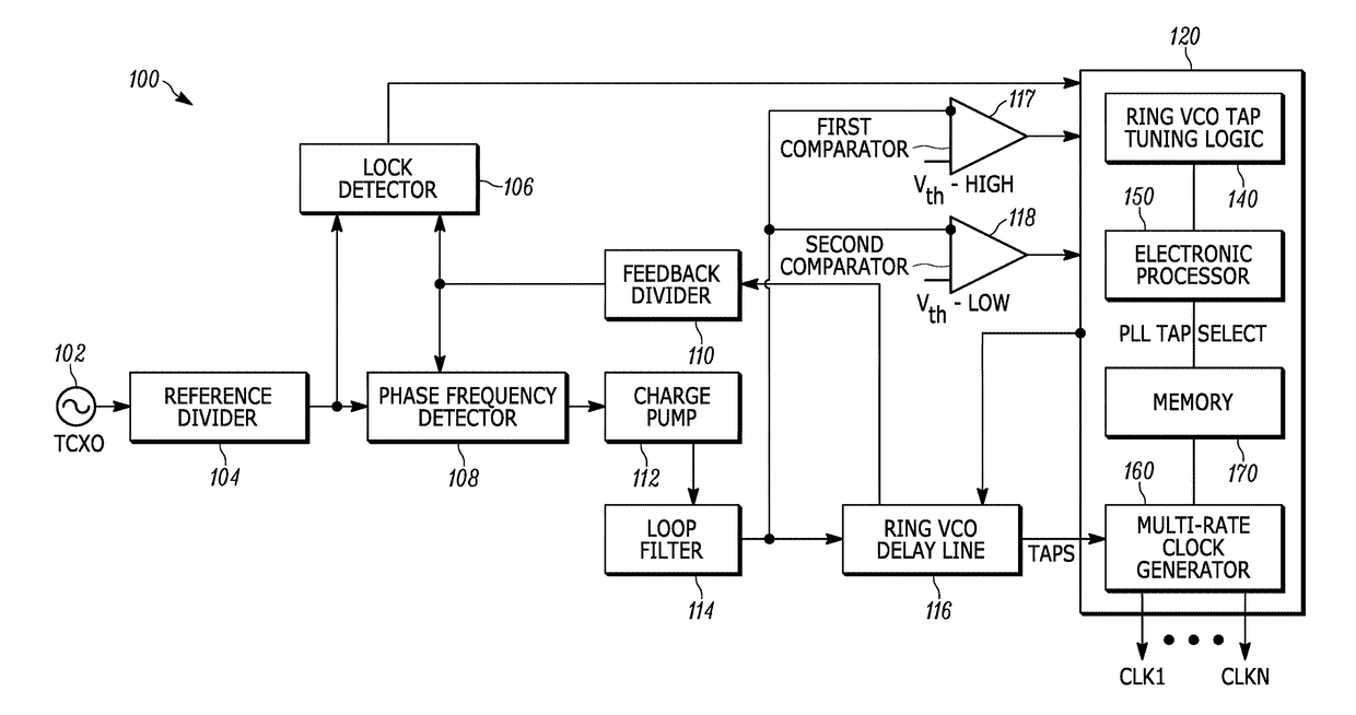
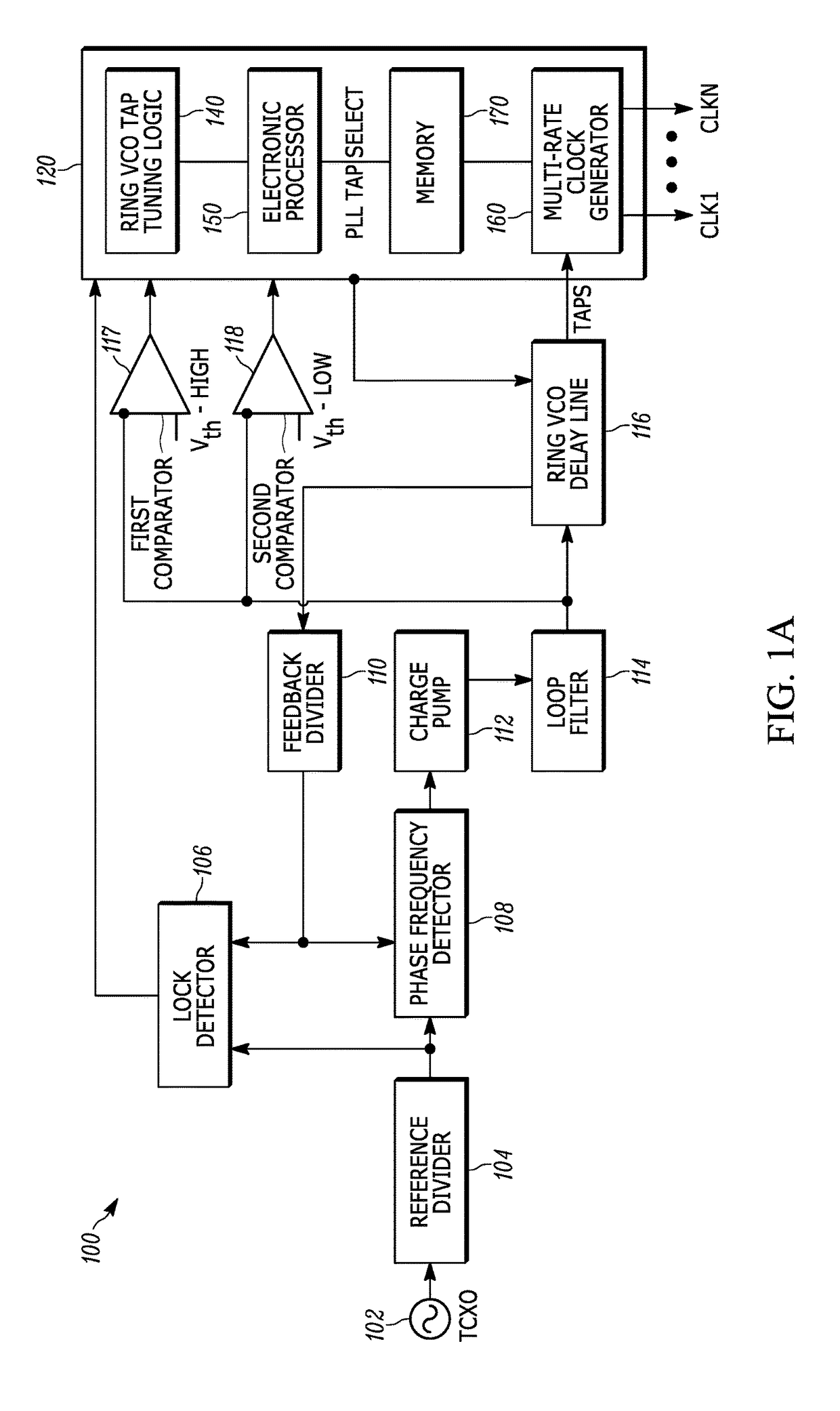
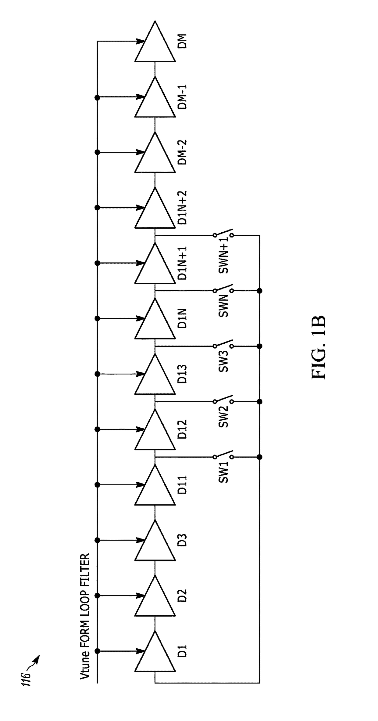
[0011]One exemplary embodiment provides a ring voltage-controlled oscillator based phase-locked loop with an integrated multi-rate clock generator. The ring voltage-controlled oscillator based phase-locked loop includes a delay line having a length extending beyond a predetermined length required for operation of the phase-locked loop; a tap tuning logic circuit coupled to the delay line; and an integrated digital multi-rate clock generator coupled to the delay line. The delay line is configured to receive a tuning voltage from the loop filter circuit and generate a plurality of tapped output signals. The digital multi-rate clock generator receives the plurality of tapped output signals and creates a plurality of clock signals.

[0012]Another exemplary embodiment provides a method of generating a multi-rate clock signal. The method includes providing a delay line for a phase-locked loop and that has a length extending beyond a predetermined length required for operation of the phase-l...


PUM


Abstract

A method and device for generating a multi-rate clock signal using a ring voltage-controlled oscillator based phase-locked loop is provided. The device includes a delay line having a length extending beyond a predetermined length required for operation of the phase-locked loop. The device further includes a tap tuning logic circuit coupled to the delay line. The delay line receives an input signal and a tuning voltage from the phase frequency detector, charge pump and loop filter circuits and generates a plurality of tapped output signals. The plurality of tapped output signals is received by the integrated digital multi-rate clock generator configured to create a plurality of clock signals.

Description

BACKGROUND[0001]Phase-locked loops (PLLs) are used in many communication systems. A phase-locked loop or phase lock loop (PLL) is a control system that generates an output signal whose phase is related to the phase of an input signal. A phase-locked loop may be used to maintain timing integrity and clock synchronization. Ring oscillator-type, voltage-controlled oscillators (VCOs) have been used in phase-locked loop systems for high-speed clock generation. An advantage of a ring oscillator-type voltage-controlled oscillator is that it may be integrated in complementary metal oxide semiconductor (CMOS) technology without introducing additional process and modeling complexity. On the other hand, disadvantages of a ring oscillator-type, voltage-controlled oscillator include jitter due to higher thermal noise and power supply noise. Also, as complementary metal oxide semiconductor process technology scales down in size, circuit complexity and operating speed increase. Additionally, ring ...

Claims


Application Information

Patent Timeline
Patent Type & Authority Patents(United States)
IPC IPC(8): H03L7/06H03L7/095H03L7/093H03L7/099H03L7/089H03K5/15H03L7/18
CPCH03L7/0996H03L7/093H03L7/095H03L7/0891H03K5/15046H03L7/1806H03L7/0995H03L7/18H03L7/0997
Inventor ROZENTAL, MARKFRANCO, RICARDOTORDJMAN, CLAUDINEYOUNG, RICHARD S.
Owner MOTOROLA SOLUTIONS INC
Learn More