Hybrid solar collector
a solar collector and hybrid technology, applied in the safety of solar heat collectors, thermal-pv hybrid energy generation, lighting and heating apparatus, etc., can solve the problems of low electricity generation efficiency of photovoltaic arrays of such hybrid devices, permanent decrease in efficiency, and hot elements of photovoltaic arrays, so as to reduce the amount of electrical energy output
- Summary
- Abstract
- Description
- Claims
- Application Information
AI Technical Summary
Benefits of technology
Problems solved by technology
Method used
Image
Examples
first embodiment
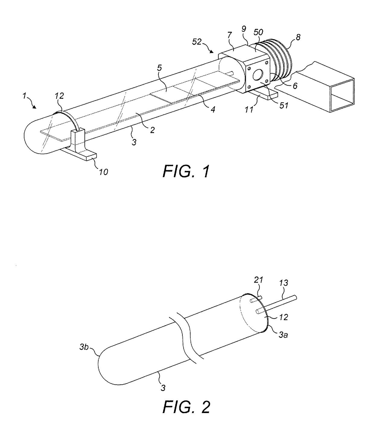
[0368]Apparatus according to a first embodiment of the present invention is illustrated in FIG. 1. FIG. 1 shows a general exterior view of a first embodiment of a hybrid solar energy converter 1 according to the present invention.
Overview
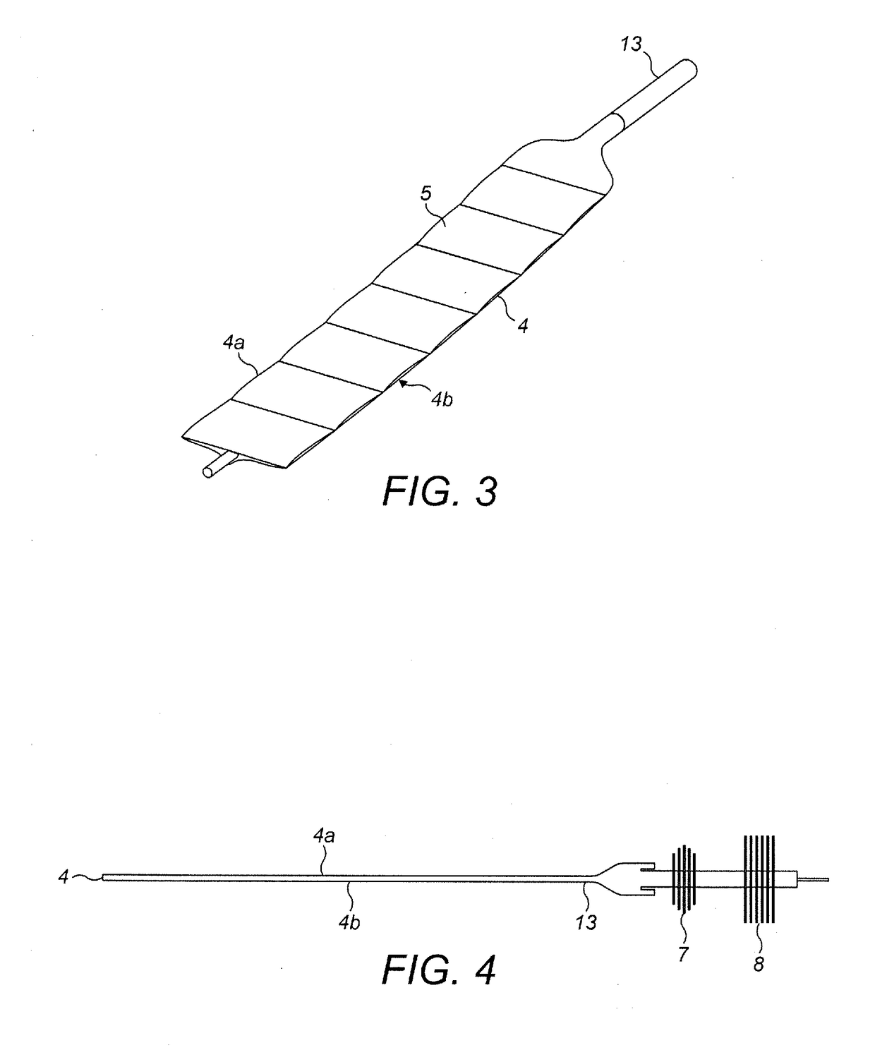
[0369]In the first embodiment, the hybrid solar energy converter 1 includes a solar energy collector assembly 2 housed within a sealed transparent tube 3. The solar energy collector assembly 2 includes a heat transport element 4 and an array of photovoltaic elements 5 mounted on an upper surface of the heat transport element 4. The hybrid solar energy converter 1 also includes a heat exchange assembly 6 at one end of the transparent tube 3. One end of the solar energy collector assembly 2 is connected to the heat exchange assembly 6. In one example the photovoltaic elements 5 may be formed of silicon. In another example the photovoltaic elements 5 may be formed of gallium arsenide. In other examples, photovoltaic elements formed of other semiconduct...
second embodiment
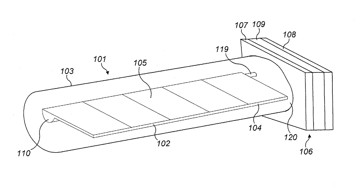
[0487]Apparatus according to a second embodiment of the present invention is illustrated in FIG. 10. FIG. 10 shows a general exterior view of a second embodiment of a hybrid solar energy converter 101 according to the present invention.
Overview
[0488]In the second embodiment, the hybrid solar energy converter 101 includes a solar energy collector assembly 102 housed within a sealed transparent tube 103. The solar energy collector assembly 102 includes a heat transport element 104 and an array of photovoltaic elements 105 mounted on an upper surface of the heat transport element 104. The hybrid solar energy converter 101 also includes a heat exchange assembly 106 at one end of the transparent tube 103. One end of the solar energy collector assembly 102 is connected to the heat exchange assembly 106. Similarly to the first embodiment, in different examples the photovoltaic elements 105 may be formed of silicon, or gallium arsenide, or other suitable semiconductor materials. In other ex...
third embodiment
[0642]Apparatus according to a third embodiment of the present invention is illustrated in FIG. 20. FIG. 20 shows a general exterior view of a third embodiment of a hybrid solar energy converter 201 according to the present invention.
Overview
[0643]In the third embodiment, the hybrid solar energy converter 201 includes a solar energy collector assembly 202 housed within a sealed transparent tube 203. The solar energy collector assembly 202 includes a heat transport element 204 and an array of photovoltaic elements 205 mounted on an front surface of the heat transport element 204, the front surface being the surface exposed to incident solar radiation in use. The hybrid solar energy converter 201 also includes a heat exchange assembly 206 at one end of the transparent tube 203. One end of the solar energy collector assembly 202 is connected to the heat exchange assembly 206. Similarly to the first and second embodiments, in different examples the photovoltaic elements 205 may be forme...
PUM
 Abstract
Description
Claims
Application Information
 - R&D
- Intellectual Property
- Life Sciences
- Materials
- Tech Scout
- Unparalleled Data Quality
- Higher Quality Content
- 60% Fewer Hallucinations
Browse by: Latest US Patents, China's latest patents, Technical Efficacy Thesaurus, Application Domain, Technology Topic, Popular Technical Reports.
© 2025 PatSnap. All rights reserved.Legal|Privacy policy|Modern Slavery Act Transparency Statement|Sitemap|About US| Contact US: help@patsnap.com


