
Energy harvesting cochlear implant

a cochlear implant and energy harvesting technology, applied in the field of totally implantable cochlear implants, can solve the problems of reducing cosmetic appeal, affecting the hearing of patients, so as to improve the hearing of patients

Active Publication Date: 2017-04-25
KULAH HALUK +2
View PDF9 Cites 3 Cited by
  • Summary
  • Abstract
  • Description
  • Claims
  • Application Information

AI Technical Summary

Benefits of technology

The present invention is a cochlear implant that reduces the need for a battery to power it. Instead, a piezoelectric transducer is used to convert acoustic waves to voltage outputs, which are then used to stimulate the auditory nerves. This technology has the advantage of higher voltage output potential than other energy harvester principles. The transducer consists of at least one base attached onto a vibrating element of the auditory system, an array of cantilever beams with a predetermined natural frequency, and a piezoelectric piece bonded to the cantilever beams. Each cantilever beam has an associated harvester electrode to harvest the voltage produced by the piezoelectric piece. The beams vibrate in transverse direction, providing space for large amplitude vibrations and a high stress in regions around the fixed end. This results in a highly efficient and effective cochlear implant that does not require batteries.

Problems solved by technology

Hearing impairment is a common disease affecting the patient's quality of life by limiting the social interaction of him / her with the environment.
However since the microphone is mounted outside the body it prevents patients' continuous access to sound (while swimming, showering etc.), and constitutes a potential for hardware damage and decreases cosmetic appeal [9].
Although the microphone used in conventional cochlear implants which is mounted outside the body can be reduced by using the suggested device, this device cannot eliminate the need for battery.
The reported device is not capable of generating energy for reducing the battery need of cochlear implants.
However, since a single elliptic thin element is used for detecting vibrations, it is not possible to make use of resonance phenomena for increasing the voltage output of piezoelectric element.
Therefore stimulation of the auditory nerves without processing the generated signals with electronic unit is not possible.
Therefore, again the reported device is not capable of reducing the battery need of conventional cochlear implants.
However this device again does not offer a solution to the power consumption problem of implants.
The need of a battery in cochlear implants is a problematic issue.
However, the suggested device is not capable of converting the acoustical pressure waves or vibrations of ossicular chain to meaningful potential output.
Therefore this device cannot be used as a microphone to sense the frequency of acoustical sound pressure waves.

Method used


Image

  • Energy harvesting cochlear implant
  • Energy harvesting cochlear implant
  • Energy harvesting cochlear implant

Examples


Embodiment Construction

[0018]In the following detailed description, reference is made to the accompanying drawings such that,

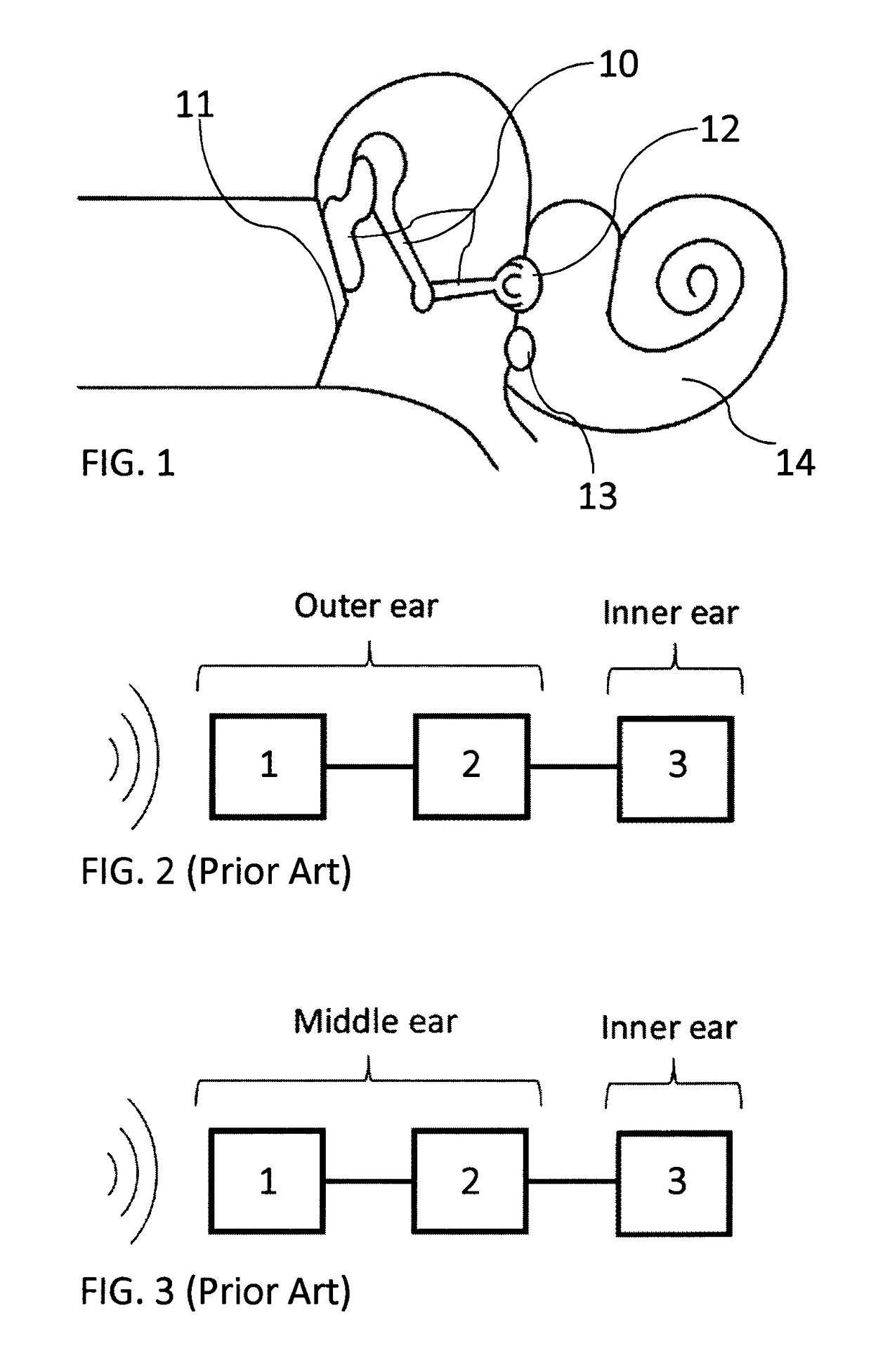
[0019]FIG. 1 is a schematic view of the human ear;

[0020]FIGS. 2 and 3 are schematic views depicting components of a cochlear implant according to the prior art;

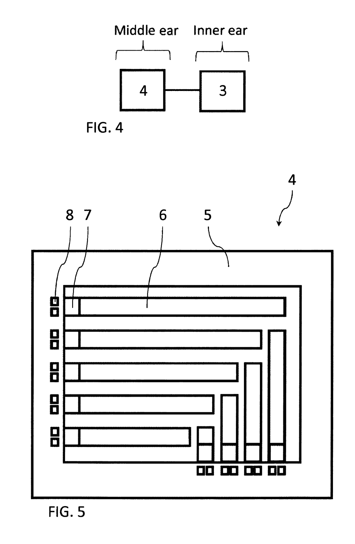
[0021]FIG. 4 is a schematic view depicting components of a cochlear implant according to the present invention;

[0022]FIG. 5 depicts a transducer according to the invention;

[0023]FIG. 6a is a side view of a beam of a transducer according to the invention in equilibrium position.

[0024]FIG. 6b is a side view of the beam in FIG. 6a in a disturbed position.

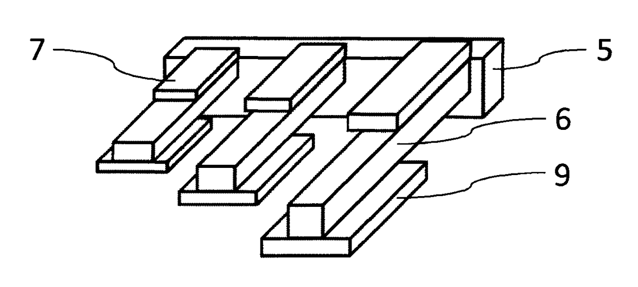
[0025]FIG. 7 depicts a beam of a transducer according to the invention in detail;

[0026]FIG. 8 is a partial view of a transducer according to the invention, depicting exemplary beams in detail;

[0027]FIG. 9 depicts another transducer according to the invention;

[0028]FIG. 10 is a schematic view of a transducer installed on the incus with partially shown electrodes mounted into coch...


PUM


Abstract

The invention is related to a totally implantable cochlear implant having a transducer which is a piezoelectric vibration energy harvester to be mounted on the ossicular chain or the tympanic membrane to detect the frequency of oscillations and generate the required voltage to stimulate the relevant auditory nerves. The invention enables patients' continuous access to sound, since it eliminates the outside components of conventional cochlear implants. The invention also eliminates the problem of battery need, since the transducer generates voltage required to stimulate auditory nerves from the vibrations of ossicular chain. The transducer is fabricated using Microelectromechanical Systems (MEMS) fabrication techniques. The invention incorporates of two main parts, a transducer acting both as a frequency detector and an energy harvester, and electrodes to stimulate the auditory nerve inside the cochlea.

Description

TECHNICAL FIELD OF INVENTION[0001]The invention is related to a totally implantable cochlear implant having a transducer which is a vibration energy harvester using piezoelectric effect and to be mounted on the ossicular chain or the tympanic membrane to detect the frequency of oscillations and generate the required impulse for the stimulation of the relevant auditory nerves. Therefore, the invention eliminates the components of the cochlear implant outside the body and the need for battery. The transducer is fabricated using Micro-Electro-Mechanical Systems (MEMS) fabrication techniques and coated with a biocompatible material.BACKGROUND OF INVENTION[0002]With the advances in MEMS technology it is possible to fabricate small size and high performance electromechanical energy harvesters converting ambient vibration to electrical potential using MEMS fabrication techniques [1]. Electromagnetic, electrostatic, and piezoelectric transduction mechanisms are the most popular approaches f...

Claims


Application Information

Patent Timeline
Patent Type & Authority Patents(United States)
IPC IPC(8): A61N1/36A61N1/378H01L41/113H02N2/18H04R25/00H04R17/00H10N30/30
CPCA61N1/36032A61N1/3785H01L41/1136H02N2/188H04R25/606H04R17/00A61N1/36038H10N30/306
Inventor KULAH, HALUKGOKSU, NEBILBEKER, LEVENT
Owner KULAH HALUK
Learn More