Material for use in a magnetic resonance system, method for producing the material and magnetic resonance system

a technology of magnetic resonance system and material, applied in the direction of magnetic bodies, instruments, magnetic/organic-metallic materials magnetism, etc., can solve the problems of incorrect diagnosis, unusable image for diagnosis purposes, and artifacts in mr images, so as to reduce mr visibility, reduce the time of relaxation, and reduce the visibility of mr imaging

Inactive Publication Date: 2017-05-09
SIEMENS HEALTHCARE GMBH
View PDF25 Cites 1 Cited by
  • Summary
  • Abstract
  • Description
  • Claims
  • Application Information

AI Technical Summary

Benefits of technology

[0017]Therefore, the locally varying susceptibility results in the generation of microscopic inhomogeneities of the magnetic field. In particular, the magnetic field varies on a characteristic length, which relates to the fineness of the intermixing and the (microscopic) geometry of the doping materials; that is, for example, with a characteristic length of less than 1 mm which results from the size of the volume. A homogeneous intermixing of this kind on a length scale of less than 1 mm can cause the material to have a reduced visibility in MR imaging, since the spins dephase more rapidly, i.e. shorter T2* relaxation times are achieved. For, example, namely the spatial resolution, i.e. the voxel size, of typical MR systems can also have an order of magnitude of approximately 1 mm. This means that, on the acquisition of MR signals, averaging or integration is performed over a corresponding imaging volume of for example 1 mm3. If the susceptibility, and hence the local magnetic field varies within this volume, the rate at which the nuclear spins contributing to the signal dephase can differ locally. For example, when using a gradient-echo sequence, this can result in different echo times. There can be a drop in signal intensity. This can reduce the MR visibility.
[0022]Ferromagnetic nanoparticles can have a particularly high magnetic susceptibility and in this way cause a particularly strong variation of the local magnetic field. In this way, the difference in the local dephasing of the nuclear spins can be particularly high and visibility in MR imaging be particularly strongly reduced. In other words, the use of ferromagnetic nanoparticles can result in a particularly short T2* relaxation time of the carrier material.
[0027]Accordingly, the doping material can, for example, be either diamagnetic (magnetic susceptibility<0) or paramagnetic (magnetic susceptibility>0). For example, the doping material can be selected from a first group of diamagnetic materials comprising the elements: graphite, bismuth. However, it is also possible for the doping material to be selected from a second group of paramagnetic materials comprising the elements: platinum, chromium, tungsten, ferritin. In particular, materials with a comparatively high absolute value for magnetic susceptibility can be used so that a local deviation of the magnetic field from the value of the basic magnetic field in the magnetic resonance system is particularly high. Accordingly, the local dephasing of the nuclear spins can be very different so that the value of the T2* relaxation time can be particularly low. It is also possible for the doping material to be palladium or to comprise carbon nanotubes.
[0029]As explained above, the material according to the aspect currently under discussion can have the effect that fine intermixing of the carrier material with the doping material causes the susceptibility to vary locally. This can cause the T2* relaxation time to be particularly short and the material to have reduced visibility in MR imaging. If the material also has a macroscopic averaged susceptibility with one of the above values, in addition to this effect of reduced MR visibility, there is also the further effect of susceptibility matching: for example, susceptibility gradients can occur at the air-tissue interface, i.e. changes to susceptibility as a function of the location. For example, on the skin surface, the value of the magnetic susceptibility changes from χ=0.38·10−6 to χ=9·10−6. This can cause the local magnetic field-value in and around this area to deviate from the value of the basic magnetic field in the MR system. The MR imaging can then have so-called susceptibility artifacts in this area, for example shifts of the MR images etc.
[0030]If, however, the material has a suitably matched value, if the material is used, for example, for components of the MR system located close to the body, such as, for example, RF coils or shim pads, it can be achieved that no significant susceptibility gradients occur at the material-tissue interface. In other words, the susceptibility mismatch can be moved to areas which do not contribute to MR imaging. This can reduce the susceptibility artifacts in the MR images.
[0041]A still further aspect relates to a magnetic resonance system with a sensitive range, wherein the magnetic resonance system is set up in order to acquire magnetic resonance data for imaging within the sensitive range, wherein the magnetic resonance system for imaging comprises components within the sensitive range. The magnetic resonance system is characterized by the fact that the components comprise a material for use in a magnetic resonance system according to an aspect discussed above. For example, the components can relate to radio-frequency coils, a table or a couch for introducing the patient into the MR system or shim pads. If a material according to the illustrated embodiments is used for the production of such components, these components can have reduced visibility in MR imaging. These components can also have magnetic susceptibility matched to the susceptibility of the environment so that susceptibility artifacts in MR imaging can be reduced.

Problems solved by technology

Imaging properties of materials located within the examination area used for MR imaging can give rise to artifacts in the MR images.
Artifacts of this kind can result in an incorrect diagnosis or render the image unusable for purposes of diagnosis.
Since, in addition to reduced visibility in MR imaging, there are also further criteria which determine suitability for use in an MR system, for example no or low electrical conductivity and no or low magnetic susceptibility, the number of usable materials is limited.
Since significantly less-expensive plastic materials, for example, cannot be used, this may result in increased costs for the production of components to use in the MR system.
In addition, it not possible to use, for example, soft and flexible plastic materials, such as those known from various aspects of daily life, since, as solid materials, these do not have reduced visibility in MR imaging.
This can result in reduced comfort and restricted design freedom when using or producing components for use in an MR system.
In addition, it is not possible to use materials that are particularly easy to produce or particularly robust or stable materials.
This can result in reduced reliability or a reduced lifetime of the components to be used in the MR system.
However, the techniques disclosed therein relate to the reduction of a susceptibility mismatch, as a result of which the static magnetic field varies on a length scale of several centimeters and deviates from the desired value of the basic magnetic field.
This can result, for example, in shifts or spatial domain distortions in MR images or have a negative influence on the quality of spectral fat saturation techniques.

Method used


Image

  • Material for use in a magnetic resonance system, method for producing the material and magnetic resonance system
  • Material for use in a magnetic resonance system, method for producing the material and magnetic resonance system
  • Material for use in a magnetic resonance system, method for producing the material and magnetic resonance system

Examples


Embodiment Construction

[0050]The present invention is explained in more detail below with reference to example embodiments and with reference to the drawings. In the figures, the same reference characters designate the same or similar elements.

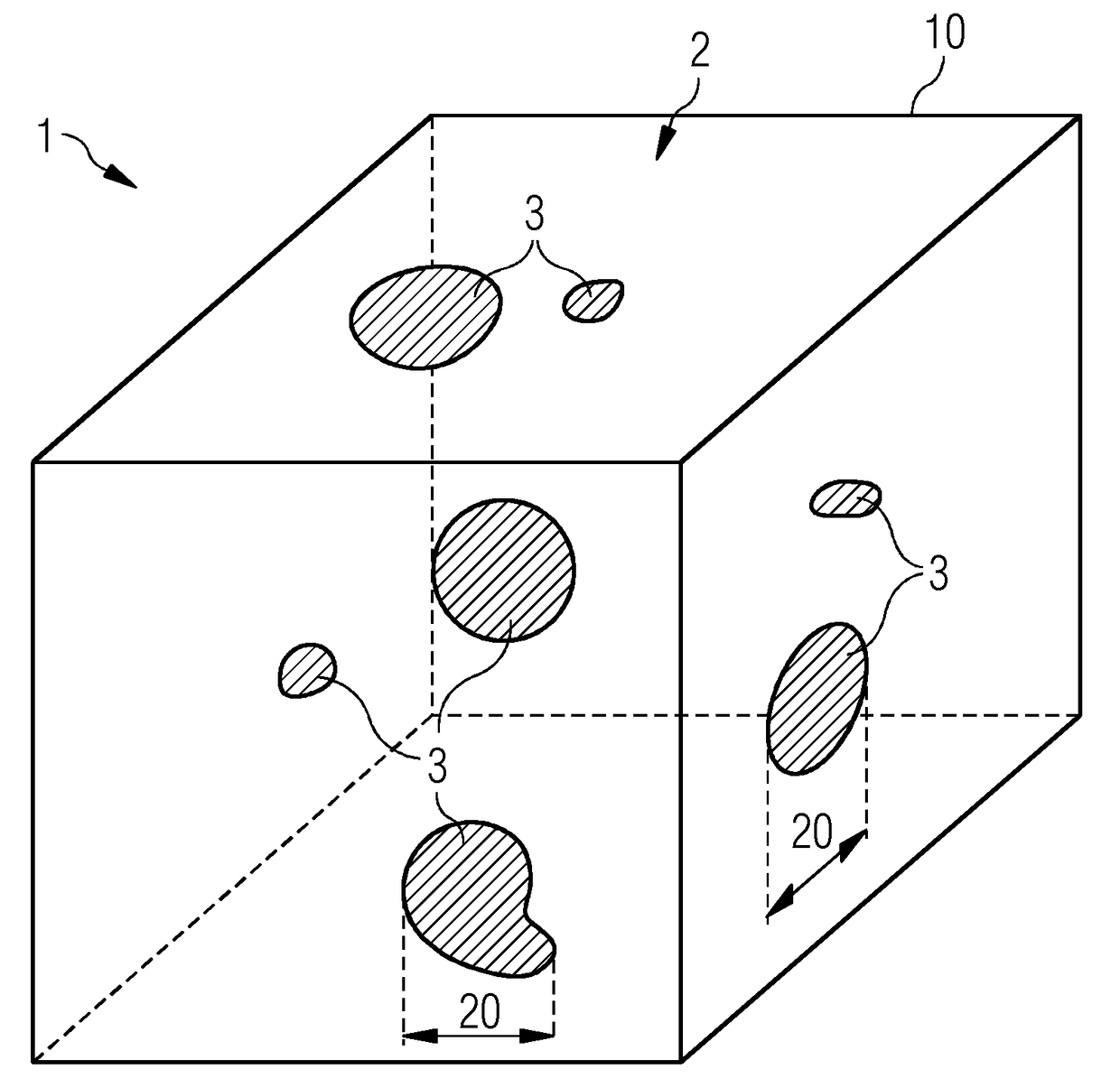
[0051]FIG. 1 shows a material 1, which is made up of a carrier material 2 and an admixed doping material 3. The doping material is depicted as embedded in particles or clusters in the carrier material 2. A particle size 20 is indicated.

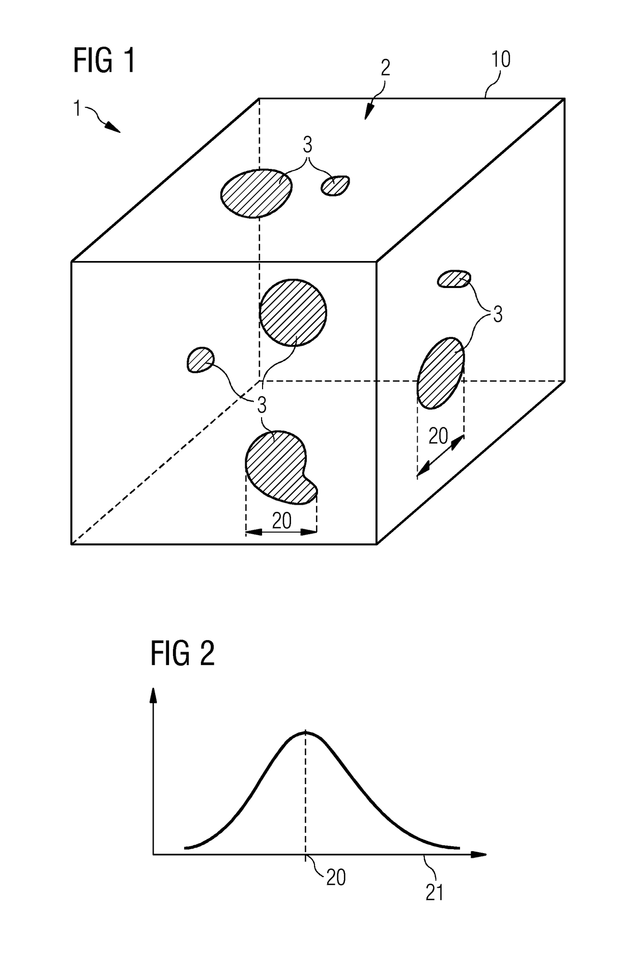
[0052]FIG. 2 shows a particle size distribution 21, i.e. a frequency of different particle sizes, by way of example. The maximum of the particle size distribution 21 can, for example, be the particle size 20. In FIG. 2, the particle size distribution 21 is described by a Gaussian curve. For example, the particle size 20 can be smaller than 200 μm, in particular smaller than 100 μm, in particular smaller than 10 μm.

[0053]With reference once again to FIG. 1, it is evident that there are local deviations in the concentration of the dopin...


PUM

PropertyMeasurementUnit
volumeaaaaaaaaaa
particle sizeaaaaaaaaaa

Abstract

A material for use in a magnetic resonance system includes a carrier material and a doping material. The carrier material and the doping material are admixed in a specific proportion. A volume of the material smaller than 1 mm2 contains a substantially homogeneous intermixing of the carrier material and the doping material.

Description

CROSS REFERENCE TO RELATED APPLICATIONS[0001]This application claims priority of German Patent Office application No. 102012204570.8 DE filed Mar. 22, 2012. All of the applications are incorporated by reference herein in their entirety.FIELD OF INVENTION[0002]Embodiments herein relate to a material for use in a magnetic resonance system, a method for producing the material and a magnetic resonance system comprising components made of the material. In particular, the embodiments relate to a material with reduced visibility in magnetic resonance imaging.BACKGROUND OF INVENTION[0003]Magnetic resonance (MR) imaging is an imaging method, which is used in many fields of medicine for examination and diagnosis. It is based on the physical effect of nuclear magnetic resonance. To this end, to acquire MR signals, a basic-field magnet applies a basic magnetic field within a region to be examined which aligns magnetic moments of nuclei, for example hydrogen nuclei H-1 or nitrogen nuclei N-14.[0...

Claims


Application Information

Patent Timeline
Patent Type & Authority Patents(United States)
IPC IPC(8): G01R33/38H01F1/00H01F1/01H01F1/42G01R33/565G01R33/34
CPCG01R33/38G01R33/565G01R33/56536H01F1/0063H01F1/01H01F1/42G01R33/34007A61B5/055G01N24/08G01R33/28
Inventor BIBER, STEPHANCANDIDUS, YVONNEFISCHER, HUBERTUSGREINER, ROBERTKUNDNER, THOMAS
Owner SIEMENS HEALTHCARE GMBH
Why Eureka
Try Eureka