System and method for generating power and enhanced oil recovery

a technology of fuel cell and system, applied in the field of solid oxide fuel cell (sofc) process and system, can solve the problems of uneconomical or physically impracticable, local power production facilities, and power conveyance infrastructure, and achieve the effects of reducing infrastructure, maximizing the number and types of potential feedstocks, and reducing the overall external requirement for fuels

Active Publication Date: 2017-05-09
SAUDI ARABIAN OIL CO
View PDF32 Cites 2 Cited by
  • Summary
  • Abstract
  • Description
  • Claims
  • Application Information

AI Technical Summary

Benefits of technology

[0014]The SOFC system and method of use produces both an FOR-quality carbon dioxide product and surplus electricity useful for other operations, including oil and gas recovery and refining. “Surplus electricity” means electricity produced in excess of the requirements of the SOFC system, including the electrochemical reactions that occur internally in the solid oxide fuel cell. The SOFC system is flexible in that it can use a variety of vaporized hydrocarbons as a feedstock, including natural gas, methane, associated gas and other hydrocarbons placed into a vapor state. Fostering on-site electrical power generation and carbon dioxide production from a single system significantly lowers the overall external requirement for fuels and chemicals to operate a recovery the system as well as eliminate the need to provide carbon dioxide for EOR. On-site production of carbon dioxide and electricity significantly reduces infrastructure and makes exploiting remote oil and gas production sites more feasible. The SOFC system also has the ability to refine carbon dioxide to a high enough purity for use as a feed stock for other chemical processes.
[0015]A pre-reformer included as part of the SOFC system addresses the variability of the types, quality and conditions of the vaporous hydrocarbon feed, which maximizes the number and types of potential feedstocks eligible for use. The inclusion of the pre-reformer in the SOFC system creates several process-related operational benefits. Higher carbon hydrocarbons (that is, non-methane hydrocarbons) are more chemically reactive than methane. Converting all of the non-methane hydrocarbons into methane stabilizes the feed composition for the solid oxide fuel cell into hydrogen, carbon oxides, water and methane. Compositional stability of the hydrocarbon feed stream to the solid oxide fuel cell, in turn, stabilizes electrical generation and the internal reformation reactions that occur in the solid oxide fuel cell. Supplying methane instead of higher carbon hydrocarbons also improves the efficiency of the solid oxide fuel resulting in greater electrical power generation. Pre-reforming the feed to the solid oxide fuel cell also permits the solid oxide fuel cell to operate at a lower steam-to-carbon ratio (SCR) than required for full reforming of a variable hydrocarbon feed. Internal reformation of methane in the solid oxide fuel cell into hydrogen and carbon monoxide is endothermic, which removes a significant amount of heat. Less cooling overall is required for the SOFC system versus systems that do not use a pre-reformer. The pre-reformer also acts as a “sacrificial sulfur sink” to any potential sulfur breakthrough. Although embodiments of the SOFC system include desulfurization systems, the pre-reformer catalyst adds another layer of protection for the solid oxide fuel cell catalysts.

Problems solved by technology

Both crude oil and natural gas production and refining are power-intensive enterprises.
Recovery of hydrocarbon materials usually occurs in remote locations, including off-shore and away from significant population centers, where power conveyance infrastructure does not exist, is uneconomical or is physically impracticable.
Environmental conditions affect smaller, local power production facilities.
Day-to-day cooling water and air temperature variations can leave some parts of a power generation system operationally limited, for example, cooling capacity.
In addition, every location has access to hydrocarbon feed stock that is slightly different in hydrocarbon, contaminant and inert composition, making a “universal” system more difficult to design.

Method used


Image

  • System and method for generating power and enhanced oil recovery
  • System and method for generating power and enhanced oil recovery

Examples


examples

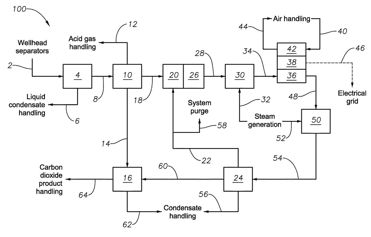
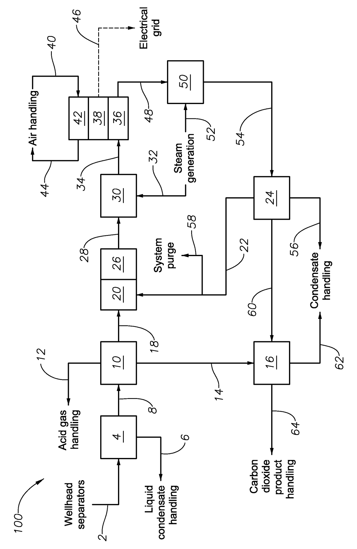
[0083]Tables 1-4 show several ASPEN process simulator (Aspen Technologies; Burlington, Mass.) modeling results for a portion of the SOFC system shown in FIG. 1. Specifically, the simulations model the behavior of the pre-reformer at various conditions, including the desulfurized process gas composition, reformation temperature and SCR. The model shows the expected reformed process gas composition. Eq. 1 is the basis for determining the SCR value for each modeling simulation. Eq. 2 is the basis for determining the value of MSR for each expected reformed process gas composition. Tables 1-4 show the entered and produced values on a dry mole percent basis.

[0084]

TABLE 1Pre-reformer Inlet and Outlet CompositionsDry mole % basis; Temperature = 300° C.DesulfurizedReformed Process GasProcess GasCompositionSCR:Composition0.51.01.5Componentsmole %mole %mole %mole %C2H456.8787.8986.8085.94C2H622.790.000.000.00C3H812.380.000.000.00C4H104.270.000.000.00C5H121.630.000.000.00CO0.000.030.010.01CO20....


PUM

PropertyMeasurementUnit
pressureaaaaaaaaaa
temperatureaaaaaaaaaa

Abstract

A method for producing a purified carbon dioxide product suitable for EOR and surplus electricity uses a vaporous hydrocarbon feed and a SOFC system. A SOFC system includes a condensate removal system, an acid gas removal system, a hydrodesulfurization system, a sorption bed system, a pre-reformer, a solid oxide fuel cell, a CO2 separations system and a CO2 dehydration system operable to form the purified carbon dioxide product, where the SOFC system is operable to produce surplus electricity from the electricity produced by the solid oxide fuel cell. A method of operating the pre-reformer to maximize the internal reforming capacity of a downstream solid oxide fuel cell uses a pre-reformer fluidly coupled on the upstream side of a solid oxide fuel cell. A method of enhancing hydrocarbon fluid recovery from a hydrocarbon-bearing formation using a SOFC system.

Description

CROSS-REFERENCE TO RELATED PATENT APPLICATIONS[0001]This application claims priority from U.S. Provisional Application No. 61 / 560,619, filed Nov. 16, 2011. For purposes of United States patent practice, this application incorporates the contents of the Provisional Application by reference in its entirety.BACKGROUND OF THE INVENTION[0002]1. Field of Invention[0003]The field of invention relates to a solid oxide fuel cell (SOFC) process and system. More specifically, the field relates to using a SOFC process and system using a vaporous hydrocarbon for producing electricity and carbon dioxide suitable for enhanced oil recovery (EOR).[0004]2. Description of the Related Art[0005]For long-time producing oil fields, FOR using carbon dioxide is a routine operation. Carbon dioxide injection repressurizes the field and fosters chemical reactions in the hydrocarbon-bearing formation that encourages additional hydrocarbon production. Purified carbon dioxide—at least 95 mole percent purity—is us...

Claims


Application Information

Patent Timeline
Patent Type & Authority Patents(United States)
IPC IPC(8): H01M8/06H01M8/18E21B43/16H01M8/0612H01M8/0662H01M8/0668C01B3/38H01M8/04089E21B43/34H01M8/124C01B32/50
CPCH01M8/0675C01B3/38C01B31/20E21B43/164E21B43/34H01M8/04097H01M8/0618H01M8/0668H01M8/0681H01M8/0687H01M8/18C01B2203/0233C01B2203/04C01B2203/0475H01M2008/1293Y02P90/70C01B32/50Y02E60/50H01M8/0637E21B43/40C01B3/48C01B2203/0261C01B2203/0283C01B2203/066
Inventor JAMAL, AQILPHAM, THANGHARALE, AADESH
Owner SAUDI ARABIAN OIL CO
Why Eureka
Try Eureka