
Lead frame

Active Publication Date: 2017-05-16
SDI CORPORATION
View PDF8 Cites 5 Cited by
  • Summary
  • Abstract
  • Description
  • Claims
  • Application Information

AI Technical Summary

Benefits of technology

The present invention aims to improve the adhesive strength between a lead frame and a molding compound, such as epoxy resin, while maintaining the bonding force with the bonding wires. This is achieved by modifying the layered structure of the lead frame. By doing so, delamination between the lead frame and molding compound after moisture absorption is reduced, and the package product passes a more severe moisture sensitivity level when exposed to the environment. This leads to an improved reliability and durability of the package product.

Problems solved by technology

However, the adhesive strength between the silver-plated layer 72 and the molding compound 91 is insufficient.
Although the metal surface treatment can try to avoid the occurrence of delamination of the molding compound from the lead frame, the roughened surfaces reduce the bonding forces of wires welded onto the roughened metal base or the roughened silver-plated layer, such that the wire disconnection and the open circuit failure between the die and external circuit likely happen to the conventional lead frame due to the insufficient wire bonding force.

Method used


Image

  • Lead frame
  • Lead frame
  • Lead frame

Examples


example 1

[0031

[0032]The lead frame 1 of the instant example was prepared as follows.

[0033]First, a 19 millimeters×19 millimeters×0.254 millimeters metal base 11 made of copper alloy, C194, was provided.

[0034]After removal of the oil of the metal base 11 with an alkaline degreaser, the degreased metal base 11 used as a cathode and a silver plate used as an anode were immersed in an electrolyte of potassium dicyanoargentate and supplied with 2 A / m2 of direct current to form a silver-plated layer 21 on the surface of the metal base 11. A silver-plated carrier was thus obtained.

[0035]Then the silver-plated carrier was immersed in an alkaline solution at 45° C. The silver-plated carrier used as a cathode and a platinum-plated titanium electrode used as an anode were supplied with 12 A / m2 of direct current for 45 seconds, so as to form a silver oxide layer 31 on the surface of the silver-plated layer 21 of the silver-plated carrier. Accordingly, a lead frame 1 having a silver oxide layer 31 with s...

example 2

[0037

[0038]In addition to the lead frame of Example 1, a second embodiment of the lead frame was provided. The lead frame of Example 2 was mainly prepared by the method for the lead frame of Example 1. The difference between the Examples 1 and 2 was that the thickness of silver-plated layer formed on the metal base was different by controlling different time durations of supplying direct current.

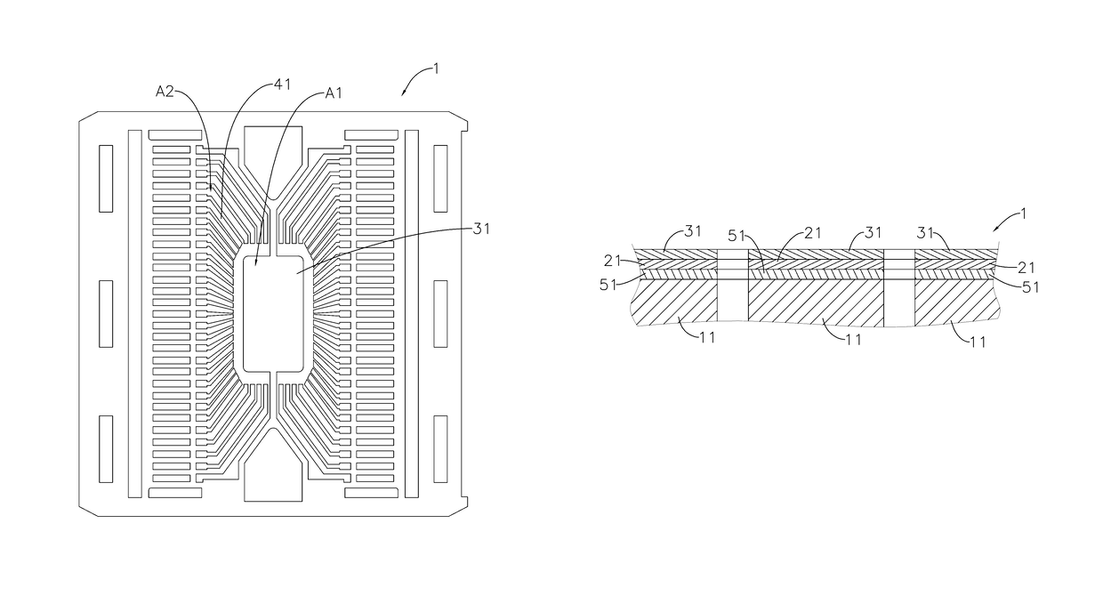
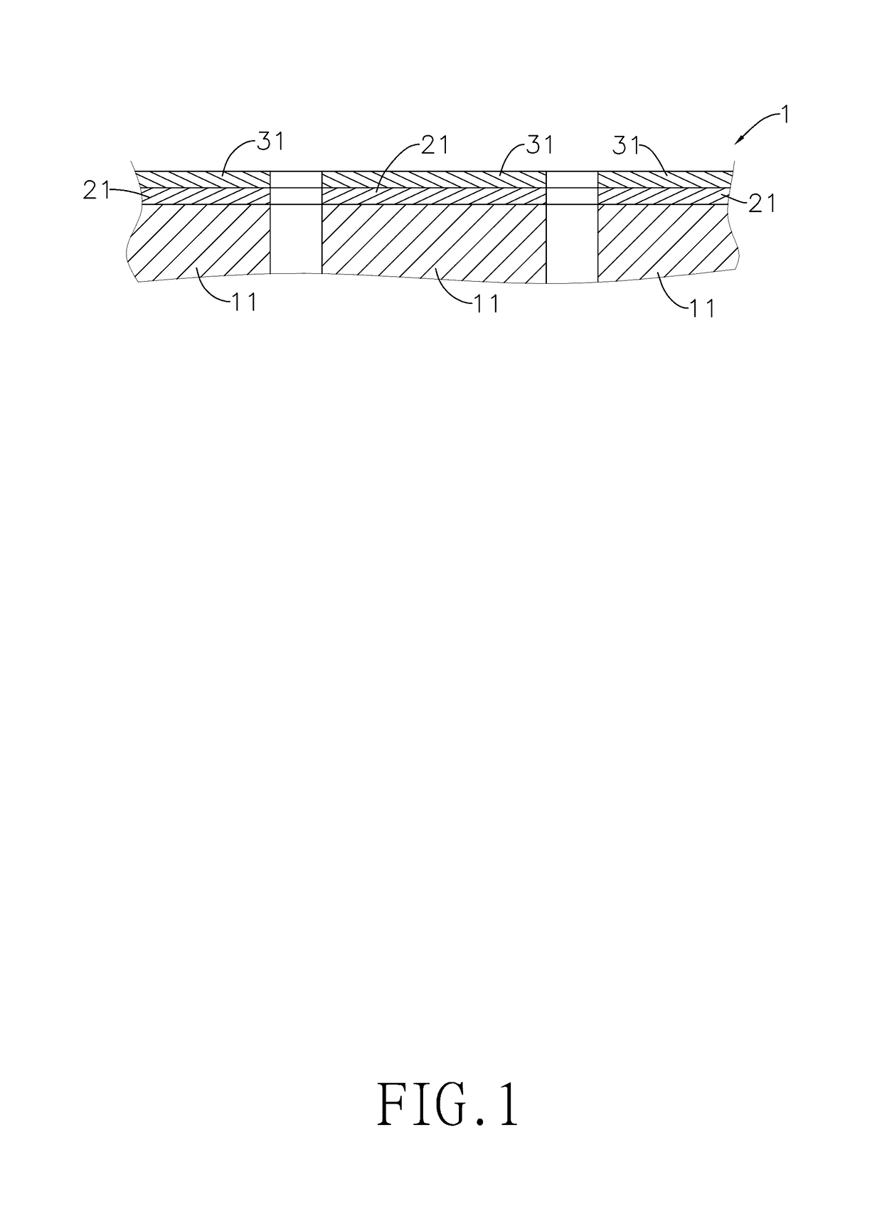
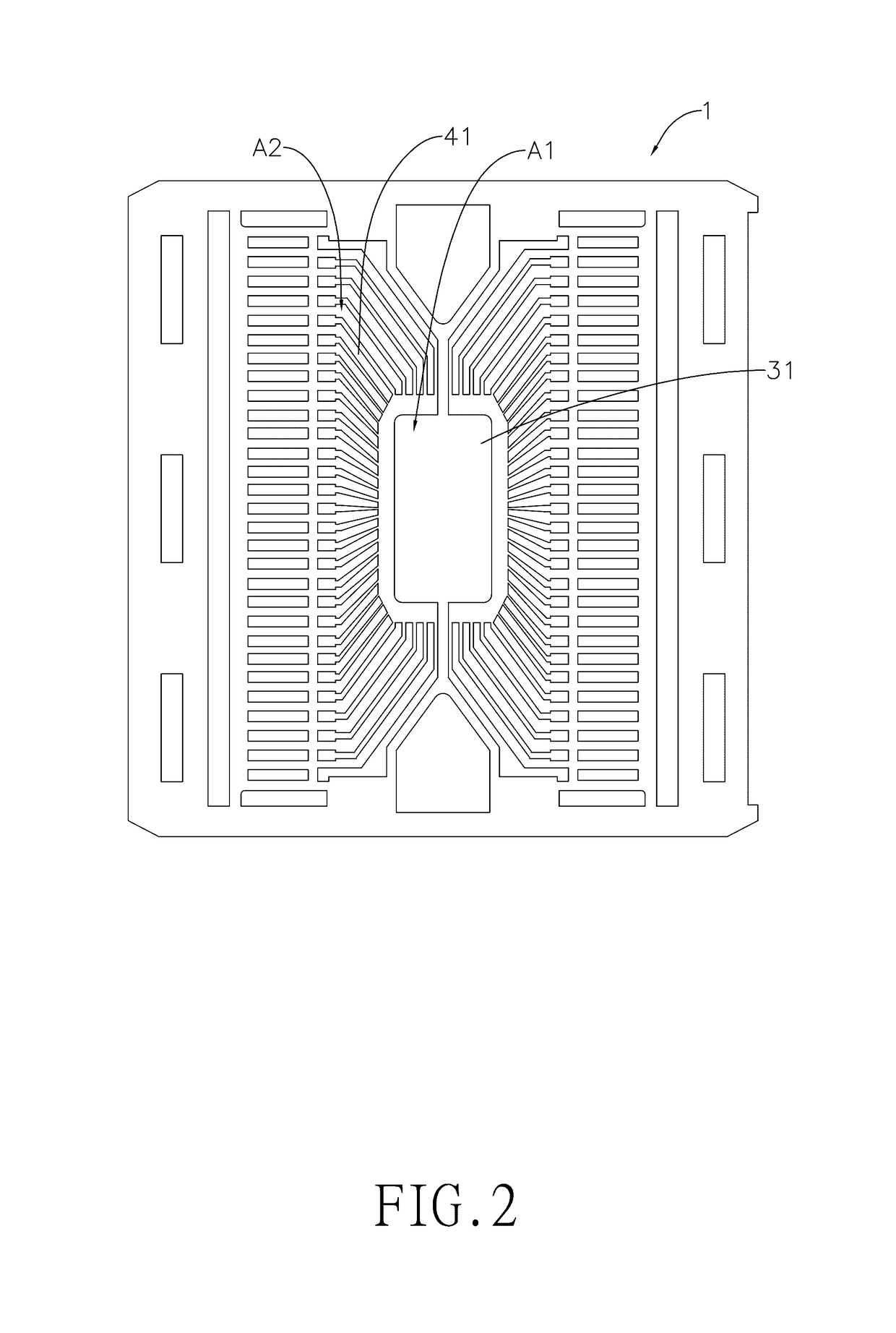
[0039]With reference to FIGS. 1 and 2, the lead frame 1 of Example 2 also comprises a metal base 11, a silver-plated layer 21 formed on the metal base 11, and a silver oxide layer 31 formed on the silver-plated layer 21. The silver-plated layer 21 is formed between the metal base 11 and the silver oxide layer 31. The silver oxide layer 31 is polar at its outer surface because of the oxygen atom bonding in the silver oxide layer 31. As measured by a thickness analyzer, the silver-plated layer 21 of the lead frame 1 of Example 2 has a thickness of 2.5 micrometers.


PUM


Abstract

A lead frame has a metal base, a silver-plated layer, and a silver oxide layer. The silver-plated layer is formed between the metal base and the silver oxide layer. The silver oxide layer has a polar outer surface and a thickness of equal to or more than 1.3 nanometers. The silver oxide layer is beneficial to increase the adhesive strength between the lead frame and the molding compound and avoid delamination of the molding compound from the lead frame, so the lead frame of the present invention can pass a more severe moisture sensitivity level when exposed to the environment.

Description

BACKGROUND OF THE INVENTION[0001]1. Field of the Invention[0002]The present invention relates to a lead frame, more particularly to a lead frame having a silver-plated layer formed on its surface.[0003]2. Description of the Prior Arts[0004]Lead frame is an important component in fabrication processes of semiconductor devices and light-emitting diodes. In addition to the function of supporting the die formed thereon, the lead frame also acts as a circuit board to transmit the inner functions of the electronic components to the outside parts.[0005]With reference to FIG. 9, a conventional lead frame comprises a metal base 71 and a silver-plated layer 72. In electronic packaging, a die 81 is mounted onto the silver-plated layer 72 of the lead frame and electrically connected with the silver-plated layer 72 by multiple bonding wires 82, so as to transmit electronic signals. In the final stage of fabrication, a molding compound 91 is employed to encapsulate the lead frame, the die 81, and...

Claims


Application Information

Patent Timeline
IPC IPC(8): H01L23/495H01L23/31
CPCH01L23/49558H01L23/49503H01L23/49582H01L23/49586H01L23/4952H01L23/3114H01L23/3142H01L2224/05582H01L2924/0541H01L2924/0665H01L2224/05639H01L2224/29139H01L2224/05155H01L2224/29639H01L2224/05139H01L2224/05147H01L2224/29583H01L24/48H01L2224/45144H01L2224/48247H01L2224/48687H01L2224/85487H01L2924/181H01L2924/35121H01L2924/01047H01L2924/00014H01L2924/00012
Inventor FANG, YA-CHENG
Owner SDI CORPORATION
Features
  • Generate Ideas
  • Intellectual Property
  • Life Sciences
  • Materials
  • Tech Scout
  • Unparalleled Data Quality
  • Higher Quality Content
  • 60% Fewer Hallucinations
Learn More