Atom cell, quantum interference device, atomic oscillator, electronic apparatus, and moving object

a quantum interference and atom cell technology, applied in the direction of preselected time interval producing apparatus, pulse automatic control, accelerators, etc., can solve the problems of reducing frequency stability, and affecting the frequency stability of excitation light passage. achieve the effect of improving frequency stability

Inactive Publication Date: 2017-05-16
SEIKO EPSON CORP
View PDF12 Cites 4 Cited by
  • Summary
  • Abstract
  • Description
  • Claims
  • Application Information

AI Technical Summary

Benefits of technology

[0010]An advantage of some aspects of the invention is to provide an atom cell that may improve frequency stability and, a quantum interference device, an atomic oscillator, an electronic apparatus, and a moving object including the atom cell.
[0013]According to the atom cell, the thickness of the thinner part provided in the wall part between the space (region) forming the metal reservoir part and the part of the outside is thinner than the thickness of the window parts, and the thinner part is radiated or cooled more easily than the window parts. Therefore, the excessive metal maybe condensed into a liquid state or solid state on the inner surface of the thinner part more easily than on the inner surfaces of the window parts. Accordingly, even when the atom cell is downsized, the excessive metal may be selectively and efficiently condensed on the inner surface of the thinner part while the condensation of the excessive metal on the inner surfaces of the window parts is reduced. As a result, frequency stability may be improved.Application Example 2
[0019]Microfabrication by etching can be performed on silicon. Therefore, even when the atom cell is downsized, the body part may be formed easily and precisely. Further, generally, the window parts are formed using glass, and the silicon is better in thermal conductivity than glass. Therefore, heat radiation of the thinner part may be made better. Further, when the window parts are formed using glass, the body part and the window parts may be easily and air-tightly bonded by anodic bonding and reliability of the atom cell may be made better.Application Example 5
[0033]With this configuration, the moving object including the atom cell that may improve frequency stability may be provided.

Problems solved by technology

However, in related art, the excessive alkali metal attaches to a passage region of excitation light, an amount of excitation light applied to the alkali metal varies and decreases, and thereby, the frequency varies and, as a result, a problem of reduction in frequency stability arises.
Particularly, when the atomic cells become smaller with recent requests for downsizing of atomic oscillators etc., the temperature difference between the excitation light passage region and the other regions becomes smaller and the alkali metal attaches to the excitation light passage region more easily, and thereby, the problem becomes significant.

Method used


Image

  • Atom cell, quantum interference device, atomic oscillator, electronic apparatus, and moving object
  • Atom cell, quantum interference device, atomic oscillator, electronic apparatus, and moving object
  • Atom cell, quantum interference device, atomic oscillator, electronic apparatus, and moving object

Examples


first embodiment

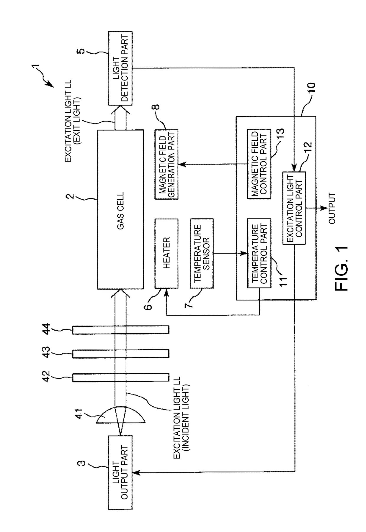
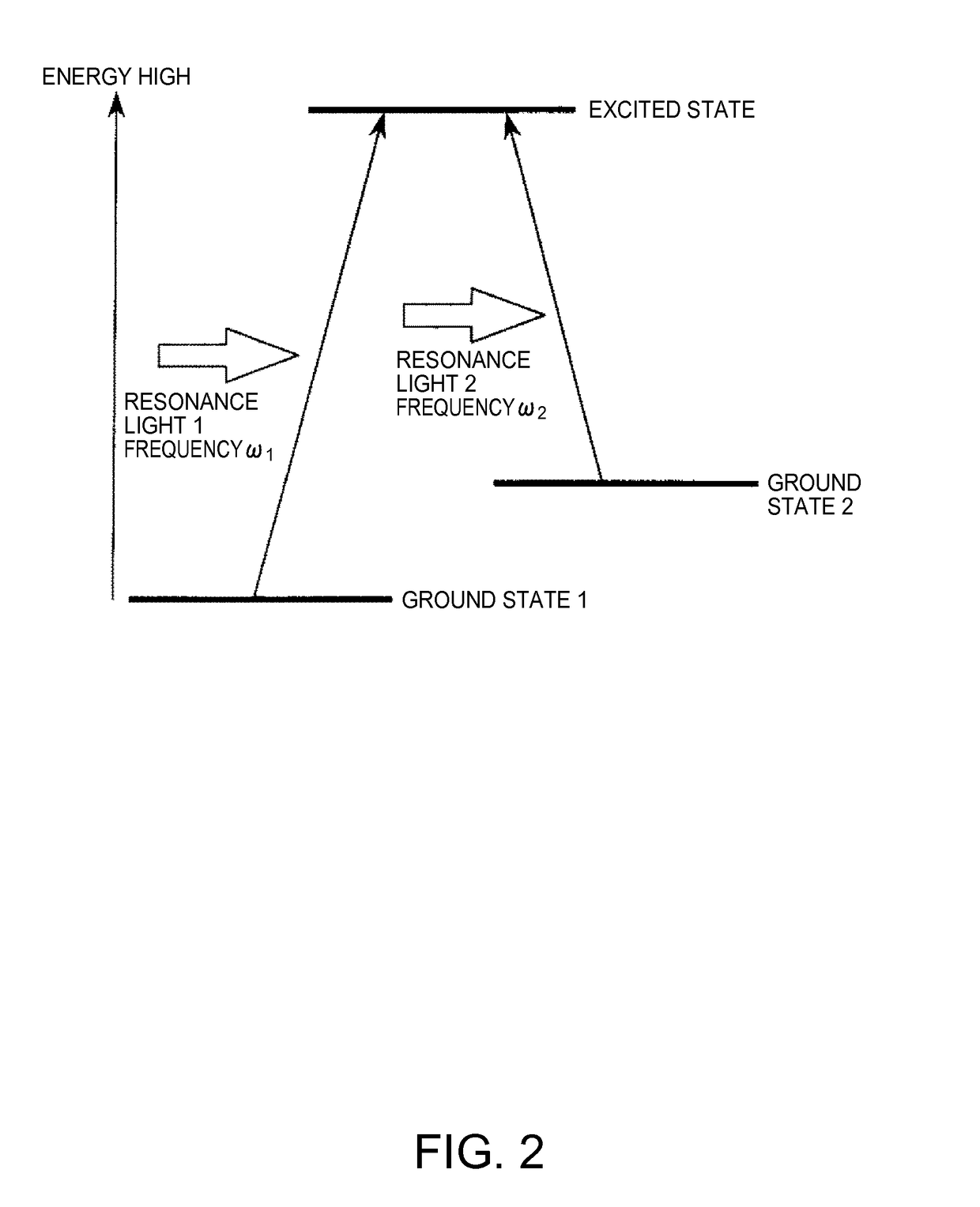
[0048]FIG. 1 is a schematic diagram showing an atomic oscillator (quantum interference device) according to the first embodiment of the invention. Further, FIG. 2 is a diagram for explanation of energy states of an alkali metal, and FIG. 3 is a graph showing a relationship between a frequency difference between two lights output from a light output part and light intensity detected in a light detection part.

[0049]An atomic oscillator 1 shown in FIG. 1 is an atomic oscillator utilizing a quantum interference effect. As shown in FIG. 1, the atomic oscillator 1 includes a gas cell 2 (atom cell), a light output part 3, optical components 41, 42, 43, 44, a light detection part 5, a heater 6, a temperature sensor 7, a magnetic field generation part 8, and a control part 10.

[0050]First, the principle of the atomic oscillator 1 will be briefly explained.

[0051]As shown in FIG. 1, in the atomic oscillator 1, the light output part 3 outputs excitation light LL toward the gas cell 2 and the lig...

second embodiment

[0114]Next, the second embodiment of the invention will be explained.

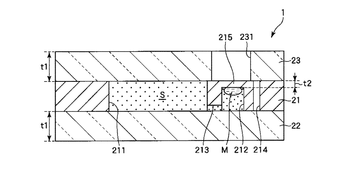
[0115]FIG. 6A is a longitudinal sectional view of an atom cell according to the second embodiment of the invention, and FIG. 6B is a cross-sectional view of the atom cell shown in FIG. 6A.

[0116]The embodiment is the same as the above described first embodiment except the difference in the configuration of the metal reservoir part of the atom cell.

[0117]Note that, in the following explanation, the second embodiment will be explained with a focus on the difference from the above described embodiment, and the explanation of the same items will be omitted.

[0118]A gas cell 2A (atom cell) shown in FIGS. 6A and 6B includes a body part 21A and a window part 23A in place of the body part 21 and the window part 23 of the first embodiment.

[0119]The body part 21A has a plate shape and, in the body part 21A, a through hole 211A that penetrates the body part 21A in the thickness direction (vertical direction) is formed. A recess...

third embodiment

[0124]Next, the third embodiment of the invention will be explained.

[0125]FIG. 7A is a longitudinal sectional view of an atom cell according to the third embodiment of the invention, and FIG. 7B is a cross-sectional view of the atom cell shown in FIG. 7A.

[0126]The embodiment is the same as the above described first embodiment except the difference in the configuration with respect to the metal reservoir part of the atom cell.

[0127]Note that, in the following explanation, the third embodiment will be explained with a focus on the difference from the above described embodiments, and the explanation of the same items will be omitted.

[0128]A gas cell 2B (atom cell) shown in FIGS. 7A and 7B includes a body part 21B and a window part 23A in place of the body part 21 and the window part 23 of the first embodiment.

[0129]The body part 21B has a plate shape and, in the body part 21B, a through hole 211B that penetrates the body part 21B in the thickness direction (vertical direction) and a re...


PUM


Abstract

A gas cell includes an alkali metal, a pair of window parts, a body part provided between the pair of window parts and forming an internal space in which the alkali metal in a gaseous state is enclosed with the pair of window parts, and a space within a recessed part forming a part of the internal space or communicating with the internal space, in which a liquid-state or solid-state alkali metal is placed, and a bottom part as a wall part between the space within the recessed part and an outside has a smaller thickness than the window parts.

Description

CROSS REFERENCE[0001]This application claim benefit of Japanese Application JP 2014-114636, filed on Jun. 3, 2014. The disclosure of the prior application is hereby incorporated by reference herein in its entirety.BACKGROUND[0002]1. Technical Field[0003]The present invention relates to an atom cell, a quantum interference device, an atomic oscillator, an electronic apparatus, and a moving object.[0004]2. Related Art[0005]As oscillators having high-accuracy oscillation characteristics on a long-term basis, atomic oscillators that oscillate based on energy transition of atoms of alkali metals including rubidium and cesium are known.[0006]Generally, the operation principle of the atomic oscillators is roughly classified into a system using a double resonance phenomenon by light and microwave and a system using a quantum interference effect (CPT: Coherent Population Trapping) by two kinds of lights having different wavelengths.[0007]In either system of atomic oscillator, typically, an a...

Claims


Application Information

Patent Timeline
Patent Type & Authority Patents(United States)
IPC IPC(8): H01S1/06H03L7/26G04F5/14
CPCH03L7/26G04F5/145H01S1/06
Inventor NAKAJIMA, TAKUYA
Owner SEIKO EPSON CORP
Why Eureka
Try Eureka