Fluid characteristic indicator

a characteristic indicator and fluid technology, applied in the field of apparatus and methods for measuring and indicating the characteristic of body fluids, can solve the problems of inability to accurately detect the characteristic of fluids, etc., to achieve faster and more accurate saturation, smooth out the flow, and maximize efficiency

Active Publication Date: 2017-05-23
CRITICAL DEVICE CORP
View PDF15 Cites 7 Cited by
  • Summary
  • Abstract
  • Description
  • Claims
  • Application Information

AI Technical Summary

Benefits of technology

[0011]These characteristics of the diffuser structure and its cooperation with the housing, including the small infilled space in the interior of the indicator and the fluid pathways channeling and directing the flow of the fluid, may advantageously allow the indicator to produce a usable measurement with a smaller volume of fluid than would otherwise be required. Fluid is efficiently directed through the body using tracks, pathways and specific internal geometries that allow a very small volume of fluid to be transferred to the indicating element. In some examples, less than a drop of fluid is needed to initiate a color change.
[0012]In addition, the control of fluid flow may help avoid damage to the indicating element, which may be delicate, from forces imparted by fluid movement. In addition, the fluid pathways provided by the diffuser and the housing allow the indicator element to be exposed from the interior surface. This helps segregate the fluid on interior side of the indicating element, so that the indicator element is not viewed through the fluid. Gastric fluid often has a color (which may, for example, be caused by the presence of blood or other materials) and the color of the aspirate may affect the color change of the indicating element. Allowing the fluid to contact the indicating element from the reverse or interior, non-viewed side, prevents transfer of the color of the aspirate itself to the indicating element. This may advantageously prevent the color of the fluid under test or contaminants therein from affecting the measurement or indication.
[0013]In some embodiments, a filter is provided to limit exposure of the indicating element to fluid contents that may spuriously affect the indication is provides. For example, the filter may prevent materials that might otherwise impart a color change, other than that produced by the intended color reaction or other measurement indication of the indicating element, from reaching the indicating element.
[0015]In some embodiments, the diffuser serves as the closure or end cap at the proximal end of the indicator and extends into the fluid chamber or passageway. A connection tube section of the diffuser serves as the proximal port of the indicator. A set of supports mechanically connect the connection tube section to the indicating element section of the diffuser. The connection tube section thus forms a part of the fluid passageway or chamber. The supports divide the fluid passageway into sections, e.g., quadrants. The sectionalization of the fluid passageway may advantageously evenly split the vacuum pressure coming from the syringe or other vacuum source to ensure that the fluid is aspirated evenly through the device.

Problems solved by technology

Although a practitioner may obtain a sample of a fluid from a medical or veterinary patient and order a variety of laboratory tests thereon, the processing of the sample in the clinic, its transportation to the laboratory, processing and analysis in the laboratory, and reporting of results all cause delay and expense.
For example, when inserting a nasogastric tube, the tube may be undesirably positioned in the patient's lungs, instead of the stomach.
Introduction of fluid which was intended to be introduced into the patient's stomach into the lung instead may be disastrous.
Although there are a variety of supplies and equipment that could, in theory, be used in a clinical setting to measure a fluid characteristic, it is not always convenient or safe to perform reliable and accurate measurements.
Test equipment may not necessarily be available in the clinic at the time it is needed, may require calibration or preparation of the equipment or accessories before use, cleaning after use, or non-trivial training of personnel for correct measurement, operation, and interpretation of the result.
Also, the cost of some equipment makes it unaffordable in some clinics.
The test results may be needed immediately, which can make obtaining and interpreting an accurate measurement challenging.
Also, the sample itself may be unstable, either generally, over time, or as a result of exposure to air, test probes, containers, reagents, materials, or the like, which allows only limited time for performing a measurement.
Some test equipment or procedures require that the sample be handled in the open, which can result in spills and exposure of personnel to the sample, which may present chemical, biological, or radiological hazards.

Method used


Image

  • Fluid characteristic indicator
  • Fluid characteristic indicator
  • Fluid characteristic indicator

Examples


embodiment 170

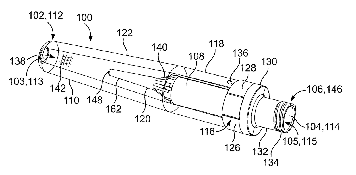
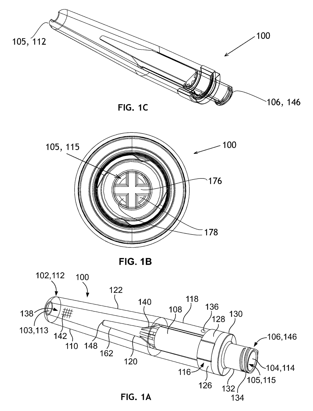
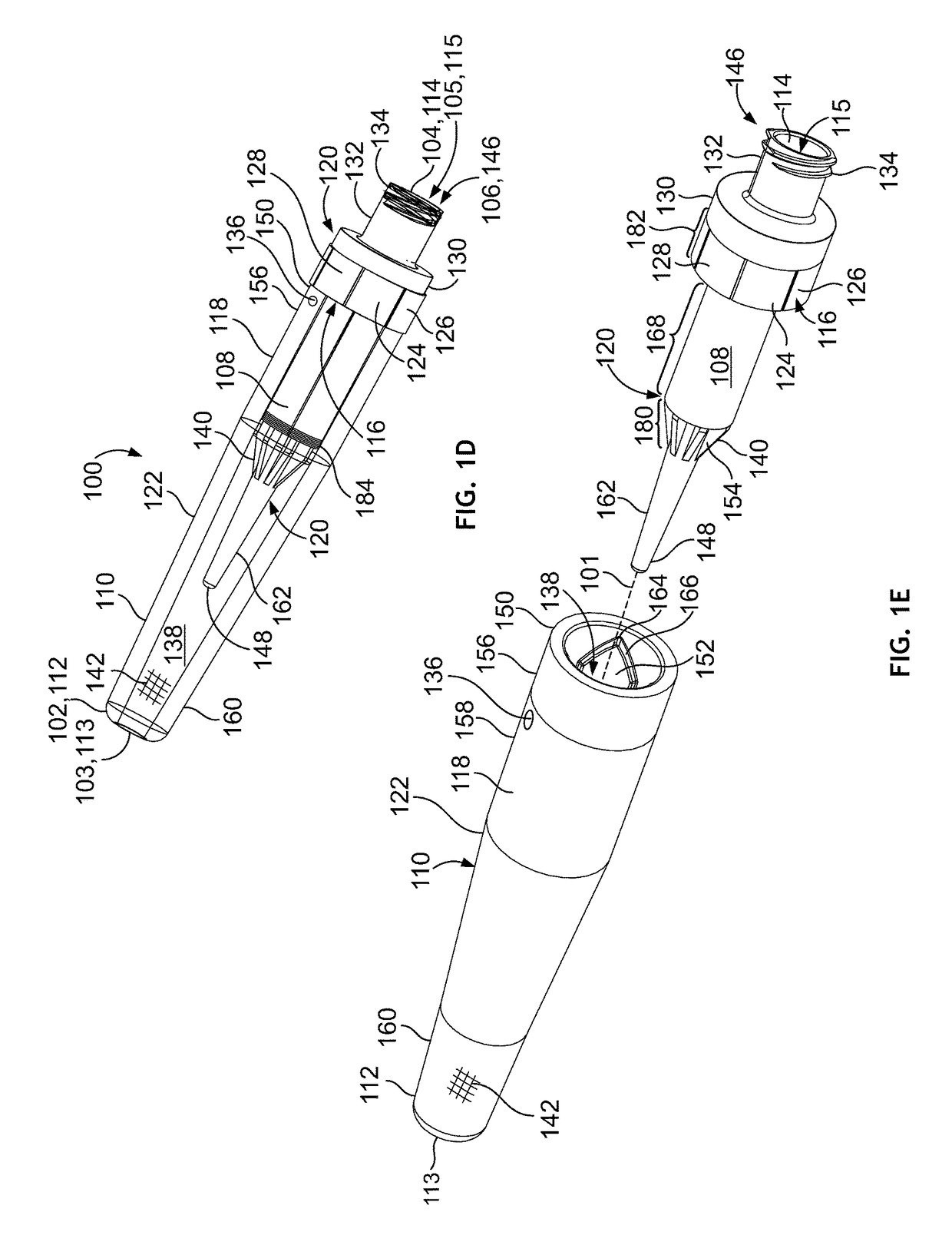
[0090]Although housing 110 is depicted in FIGS. 1A-1E, with a “catheter tip” distal end 112 configuration that accommodates frictional, sealing engagement with the fluid transport source, housing 110 could also have another structure for coupling to the fluid transport source. FIG. 2A is a side view of an embodiment 170 of a housing constructed in accordance with a further aspect of the present invention. Housing 170 is generally similar to the housing 110 of FIGS. 1A-1E, but has a male Luer lock fitting 174 at the distal end 172, instead of the catheter tip. Housing 170 is generally similar to housing 110 of FIGS. 1A-1E as heretofore described, and except for the differences explained below, the foregoing description of housing 110 housing 170, mutatis mutandis, and is hereby incorporated by reference. The Luer lock 174 may mate with a complementary fitting on the fluid transport source. The positive mating avoids the need to rely on friction alone for a seal and may avoid malfunct...

embodiment 190

[0097]FIG. 2B is an isometric view, and FIG. 2C is a side view, of a further embodiment 190 of a housing which is similar to the housing 110 of FIGS. 1A-1E but which provides a central fluid passage 192 of modified cross section. Housing 190 is generally similar to housing 110 of FIGS. 1A-1E as heretofore described, and except for the differences explained below, the foregoing description of housing 110 is applicable to housing 190, mutatis mutandis, and is hereby incorporated by reference. A fluid passage 192, which functions in a manner similar to the fluid passage 138 of the housing 110 of FIGS. 1A-1E extends between a distal-end or intake port 198 and a proximal end opening 188. FIG. 2D is a view of housing 190 looking into the proximal end opening 188 as shown by view lines 2D-2D of FIG. 2C. FIG. 2E is a view of housing 190 looking into the distal end opening 198 as shown by view lines 2E-2E of FIG. 2C. FIG. 2F is a cutaway view of the housing 190 of FIGS. 2B and 2C, taken alon...

embodiment 120

[0105]In an embodiment 120 of a diffuser constructed according to one aspect of the invention, the indicating element section 168 may have a generally star-shaped cross-section formed by spines, ridges, or vanes 140 extending radially from a central core along the length of indicating element section 168. The vanes 140 further extend longitudinally between the indicating element section 168 to the tip section 162 through the second transition section 180, tapering in diameter. The configuration of vanes 140 form plural substantially independent diffuser fluid channels 154, which may be used to independently expose different indicating elements 108 or portions thereof. The plural independent diffuser fluid channels 154 could also be used to route fluid from different respective fluid sources to one or more indicating elements; a modification of the housing would be needed to receive fluid from plural sources and separately convey the fluid to respective fluid channels. Other diffuser...


PUM

PropertyMeasurementUnit
helical shapeaaaaaaaaaa
suctionaaaaaaaaaa
vacuum pressureaaaaaaaaaa

Abstract

A fluid characteristic indicator for measuring and indicating a characteristic of body fluid from a medical or veterinary patient has a tubular housing with suction and fluid inlet ports at opposite ends and a fluid characteristic indicating element disposed within. A diffuser supports the indicating element and has at least one fluid channel to direct fluid toward the indicating element. The fluid channel may be formed as a spiral or helix, or as a plurality of longitudinal fluid channels. The housing and the diffuser may have additional structures forming channels that cooperatively direct fluid toward the indicating element. The diffuser may occupy nearly all the interior volume of the housing. Control of the fluid flow may make exposure and saturation of the indicator more accurate, avoid spurious indications due to the color of the fluid itself, and reduce the amount of fluid sample needed to obtain an indication or measurement.

Description

CROSS REFERENCE TO RELATED APPLICATIONS[0001]This application claims the benefit under 35 U.S.C. 119(e) of U.S. Provisional Application No. 61 / 915,151 filed 12 Dec. 2013, which is hereby incorporated by reference.FIELD OF THE INVENTION[0002]This application relates to apparatus and methods for measuring fluid characteristics, and more particularly to apparatus and methods for measuring and indicating a characteristic of a body fluid such as may be obtained from a medical or veterinary patient.BACKGROUND OF THE INVENTION[0003]Although a practitioner may obtain a sample of a fluid from a medical or veterinary patient and order a variety of laboratory tests thereon, the processing of the sample in the clinic, its transportation to the laboratory, processing and analysis in the laboratory, and reporting of results all cause delay and expense. In some cases, it is desirable for the clinician to obtain an immediate and reliable indication of one or more characteristics of a fluid obtained...

Claims


Application Information

Patent Timeline
Patent Type & Authority Patents(United States)
IPC IPC(8): A61B5/00A61J15/00G01L19/10A61B5/145A61B5/1473A61B5/06A61B5/103A61B10/00
CPCG01L19/10A61B5/14539A61B5/14735A61B5/4238A61B5/6852A61B10/0045A61B5/065A61B5/1032A61B10/007A61B10/0051A61B2010/0061A61J15/0003A61J15/0026Y10T137/8158
Inventor GILBERT, PAUL J.CHUDZIK, RAFAL
Owner CRITICAL DEVICE CORP
Why Eureka
Try Eureka