Cutting condition and tool life display device for a numerical controller

a numerical controller and display device technology, applied in the field of cutting condition display devices, can solve the problem that methods cannot be easily achieved without experience, and achieve the effect of shortening the life of the tool, facilitating the estimation of cutting conditions, and improving the durability of the tool

Active Publication Date: 2017-05-30
FANUC LTD
View PDF15 Cites 3 Cited by
  • Summary
  • Abstract
  • Description
  • Claims
  • Application Information

AI Technical Summary

Benefits of technology

[0008]Accordingly, in view of the problem of the prior art described above, the object of the present invention is to provide a cutting condition display device capable of facilitating estimation of cutting conditions that shorten the life of a tool, in order to improve the durability of the tool.
[0019]According to the present invention, there can be provided a cutting condition display device capable of facilitating estimation of cutting conditions that shorten the life of a tool, in order to improve the durability of the tool.

Problems solved by technology

However, this method cannot be easily achieved without experience.

Method used


Image

  • Cutting condition and tool life display device for a numerical controller
  • Cutting condition and tool life display device for a numerical controller
  • Cutting condition and tool life display device for a numerical controller

Examples


example 1

Display Example 1

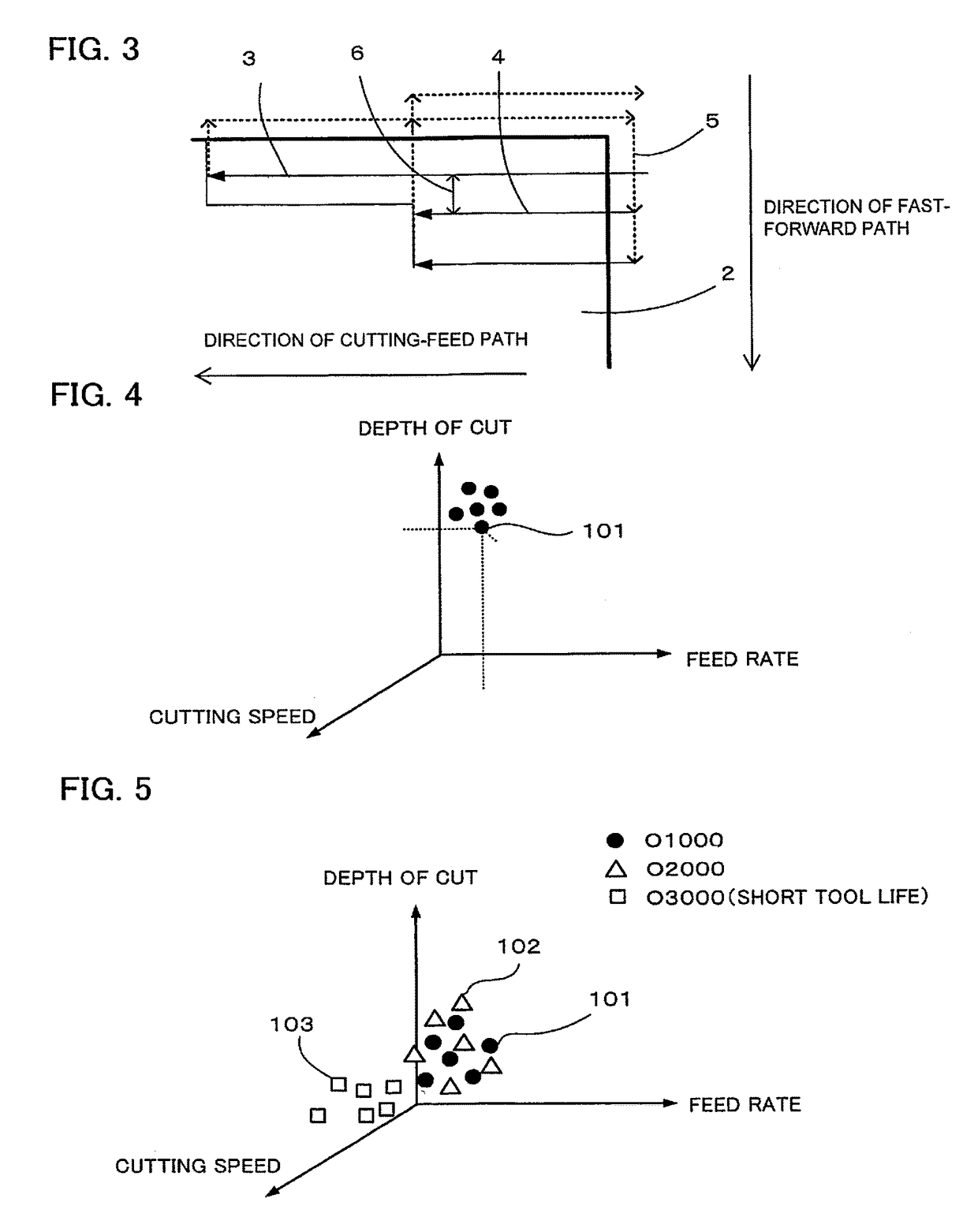
[0061]The following is a description of an example in which the cutting conditions stored in a cutting condition storage section are graphically displayed in a scattering diagram on a three-dimensional coordinate system with its coordinate axes representative of the three cutting conditions (cutting speed, feed rate, and depth of cut). FIG. 4 is a diagram illustrating the example in which the cutting conditions of a single machining program are graphically displayed in the scattering diagram on the three-dimensional coordinate system. The trend of the cutting conditions of the machining program can be confirmed by a group of plotted points. It can be seen at a glance that plots 101 of FIG. 4 tend to be unevenly distributed in the axial direction of the depth of cut. If the cutting conditions of the machining program based on a short tool life are plotted in the manner shown in FIG. 4, only the depth of cut is too great, so that the depth of cut can be estimated to b...

example 2

Display Example 2

[0062]The following is a description of an example in which the cutting conditions stored in the cutting condition storage section are graphically displayed in a scattering diagram on the three-dimensional coordinate system with its coordinate axes representative of the three cutting conditions (cutting speed, feed rate, and depth of cut). FIG. 5 is a diagram illustrating the example in which the cutting conditions of a plurality of machining programs are graphically displayed in the scattering diagram on the three-dimensional coordinate system. The cutting conditions are stored for each machining program so that a cutting condition that shortens the tool life can be estimated by comparing the machining programs based on short and long tool lives. When different machining programs are run with the same tool and if a machining program (O3000) that has led to a short tool life and machining programs (O1000 and O2000) that have led to long tool lives are plotted in the...

example 3

Display Example 3

[0063]The cutting conditions stored in the cutting condition storage section may be displayed in a bar, circle, or line graph. FIG. 6 is a diagram illustrating an example in which the cutting conditions of a plurality of machining programs are graphically displayed in a bar graph. If the machining program (O3000) that has led to a short tool life and the machining programs (O1000 and O2000) that have led to long tool lives are graphically displayed in the bar graph of FIG. 6, as in the above-described display example 2, the cutting speed of O3000 tends to be relatively high, so that the cutting speed can be estimated to be the cutting condition that shortens the tool life. Numerals 201, 202 and 203 denote the numbers of stored cutting conditions (cutting speeds in FIG. 6) of O1000, O2000 and O3000, respectively.


PUM


Abstract

A numerical controller controls a spindle and / or a movable axis of a finishing machine based on a machining program. A cutting condition display device configured to display a cutting condition for the numerical controller calculates cutting conditions including a cutting speed, a feed per spindle revolution per cutting edge of a tool, and a depth of cut for each fixed time during an operation of the finishing machine, based on any or a combination of data on the spindle, the movable axis, a cutting tool, and an object to be cut, which are held by the numerical controller. The calculated cutting condition is stored for each tool and displayed in a graph.

Description

RELATED APPLICATIONS[0001]The present application claims priority to Japanese Application Number 2013-058938, filed Mar. 21, 2013, the disclosure of which is hereby incorporated by reference herein in its entirety.BACKGROUND OF THE INVENTION[0002]Field of the Invention[0003]The present invention relates to a cutting condition display device configured to display cutting conditions obtained during actual machining or machining simulation.[0004]Description of the Related Art[0005]In conventional machining (e.g., Japanese Patent Application Laid-Open No. 07-160317), cutting conditions that shorten the life of a tool, among other cutting conditions that greatly affect the tool life, are known to be estimated from the tool wear state and past experiences. These influential cutting conditions include the cutting speed, feed per spindle revolution per cutting edge of a tool, depth of cut, spindle speed, and feed speed.[0006]During an operation or machining simulation, those cutting conditi...

Claims


Application Information

Patent Timeline
Patent Type & Authority Patents(United States)
IPC IPC(8): G05B19/4093
CPCG05B19/40937G05B2219/35252G05B2219/36283G05B2219/36284Y02P90/265Y02P90/02
Inventor KAWASHIMA, YUUSUKE
Owner FANUC LTD
Why Eureka
Try Eureka