
UAV-enforced insect no-fly zone

a technology of insect no-fly zone and insect net, which is applied in the field of uav-enforced insect no-fly zone, can solve the problems of inconvenient use, limited efficiency, and inability to prevent mosquito bites,

Inactive Publication Date: 2017-07-04
MOITIER JEAN FRANCOIS
View PDF19 Cites 18 Cited by
  • Summary
  • Abstract
  • Description
  • Claims
  • Application Information

AI Technical Summary

Benefits of technology

The patent describes a system and method for counteracting flying insects using an unmanned aerial vehicle (UAV) equipped with an imager and an embedded counteracting device. The system can identify and track insects using images captured by the imager and can perform various counteracting actions to kill, repel, or impair the insect's biological functions. The method involves acquiring images, determining if they contain an insect, and identifying the specific species or subspecies of the insect. The system can also include sensors to avoid collisions and optimize flight trajectories, and can use a ground station for additional processing. The technical effects of this patent include improved efficiency and effectiveness in identifying and counteracting flying insects, as well as improved safety and reliability for UAV operations.

Problems solved by technology

Preventing mosquito bites is therefore a major public health issue.
There are currently many mosquito control techniques available but most of them are of limited efficiency.
However, they have to be perfectly adjusted and are not convenient to use in many daily life circumstances.
Biocontrol methods, relying for example on mosquito predators or mosquito bacteria or fungi, may be effective to a certain extent, but can only lower the number of insects without eradicating them.
However, important downsides limit their use and efficiency.
The public is more and more reluctant to accept the heavy use of chemicals because they may present unwanted side-effects.
They may eventually prove harmful for humans, animals and plants.
Therefore, they have the potential to kill each and every mosquito within their range.
However these devices require relatively powerful laser beams that are dangerous for the human eye.
As a consequence they can only be operated in restricted environments free of people and animals.
However, most of such flying devices rely on a chemical action to kill the targeted insects, thus featuring all the downsides of the chemical methods.

Method used


Image

  • UAV-enforced insect no-fly zone
  • UAV-enforced insect no-fly zone
  • UAV-enforced insect no-fly zone

Examples


first embodiment

Description

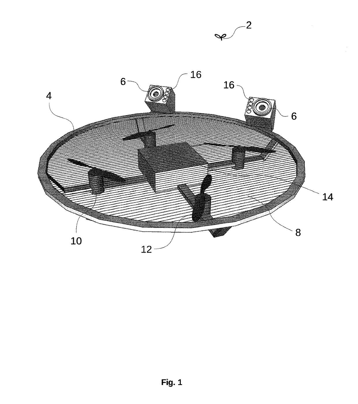
[0038]In the following description, reference is made to the accompanying drawing (FIG. 1), which form a part hereof.

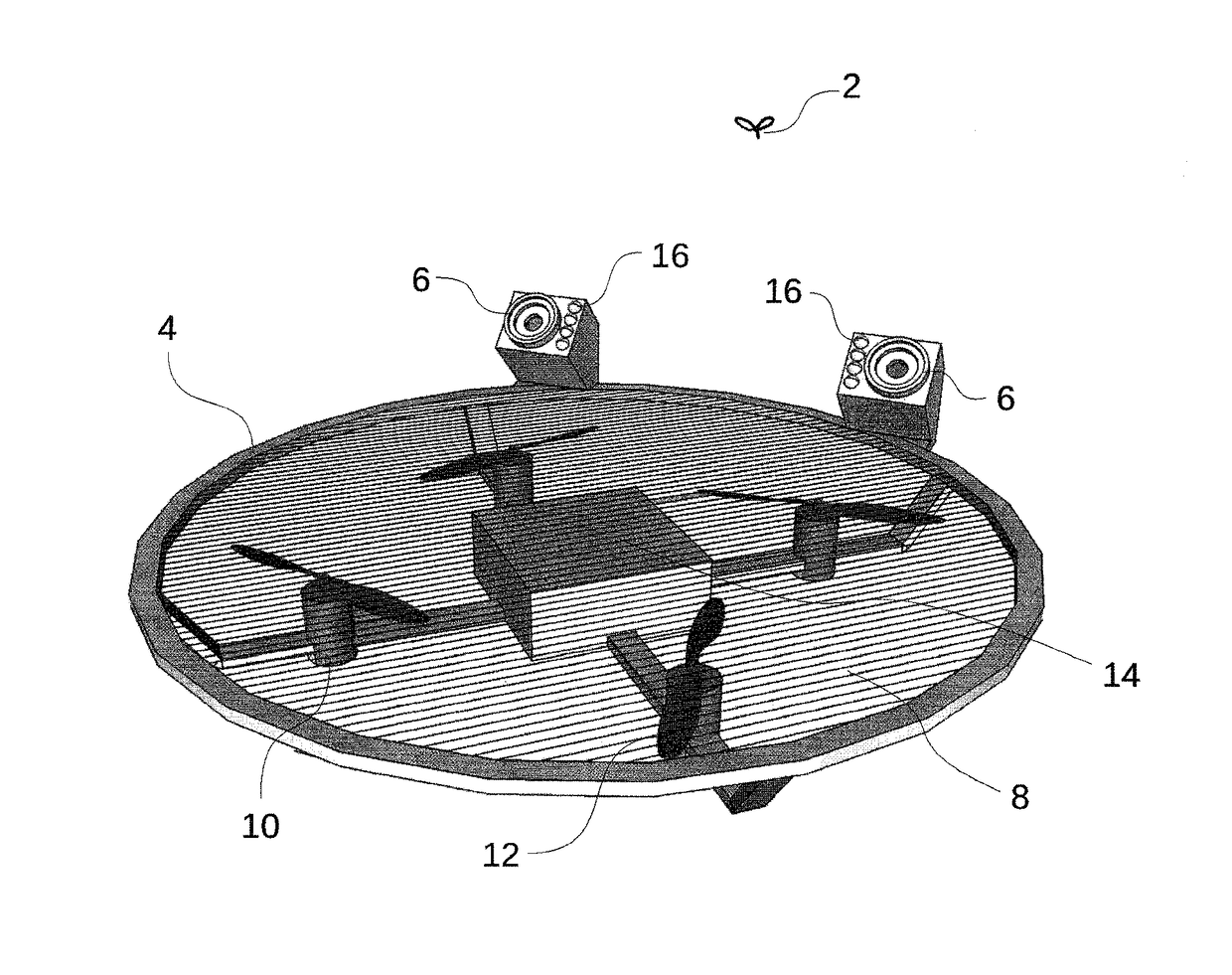
[0039]As shown in FIG. 1, a system for identifying, tracking and electrocuting female mosquitoes 2 includes in a particular embodiment a UAV 4, two infrared CMOS cameras 6, an electrified grid 8 and two processors.

[0040]This particular embodiment is designed to counteract female mosquitoes, however other embodiments may target other particular insect species or types, e.g. wasps or flies, or may target a set of different species or types.

[0041]In this particular embodiment, the UAV is an instance of a miniature quadrotor design, well known of those skilled in the art. The UAV comprises four electrical engines 10, four rotors 12 and a central unit 14. The central unit comprises a battery, four engine speed controllers and two processor boards.

[0042]The first processor board is an upper-level control board with an integrated GPU for advanced image processing....

second embodiment

[0060]As shown in FIG. 3, a system for identifying, tracking and counteracting female mosquitoes 2 or other insects includes in this particular embodiment a UAV 4, a ground station 6 and two imagers 8.

[0061]In some other approaches, the number of UAVs, imagers and processors may be different. In this particular embodiment, the UAV and the ground station each include a processor, but in some other embodiments the number of processors may be different. The ground station featured in this particular embodiment is a common type of personal computer with sufficient processing power. In other embodiments the ground station may be a more specialized unit.

[0062]In this particular embodiment, the UAV is an instance of a miniature quadrotor design, well known of those skilled in the art. The UAV features a battery, four electrical engines 10, four rotors 12 and a flight control unit 14 comprising a processor and inertial measurement unit (IMU). Other embodiments may feature different types of...

third embodiment

[0075]As shown in FIG. 4, a system for identifying, tracking and counteracting female mosquitoes or other insects includes in this particular embodiment a UAV 2 and an imagers set 4.

[0076]In this particular embodiment, the tracking and counteracting system protects a defined zone 6 against female mosquitoes.

[0077]The imagers set and the UAV each include a processor.

[0078]In some other approaches, the number of UAVs, imagers in the imagers set and processors may be different.

[0079]In this particular embodiment, the UAV is an instance of a miniature quadrotor design, well known of those skilled in the art. Other embodiments may feature different types of UAVs like ornithopter or plane, different types of rotorcrafts like hexacopter or octocopter. They may feature different types of imagers and sensors like ultrasonic distance sensors.

[0080]In the illustrated embodiment, the imagers in the imagers set each include an infrared CMOS cameras. A variety of other imagers may also be appropr...


PUM


Abstract

A system for tracking and counteracting flying insects includes an imager, a unmanned aerial vehicle with an embedded counteracting device and a processor.

Description

BACKGROUNDPrior Art[0001]The following is a tabulation of some prior art that presently appears relevant.[0002]U.S. PatentsPat. No.Kind codeIssue datePatentee6,653,971B12003 Nov. 25Guice et al.6,853,328B12003 Nov. 25Guice et al.7,501,979B12009 Mar. 10Guice et al.8,400,348B12013 Mar. 19Guice et al.8,705,017B22014 Apr. 22Hyde et al.[0003]Foreign patents documentsForeign Doc. Num. Ctry codeKind codePub. date102897323CNA2013 Jan. 30 102910292CNA2013 Feb. 6[0004]Mosquitos are the vector of several human diseases including dengue, chikungunya and malaria.[0005]Malaria alone kills more than half a million people each year around the world.[0006]Preventing mosquito bites is therefore a major public health issue.[0007]There are currently many mosquito control techniques available but most of them are of limited efficiency.[0008]Mosquito nets are of great help to repell mosquitoes. However, they have to be perfectly adjusted and are not convenient to use in many daily life circumstances.[0009...

Claims


Application Information

Patent Timeline
IPC IPC(8): A01M1/00B64C33/00B64D47/08B64D47/02B64C27/08B64C27/00B64C39/02A01M5/02
CPCA01M5/02B64C39/024B64C27/00B64C27/08B64C33/00B64D47/02B64D47/08B64C2201/12B64C2201/024B64U2101/00B64U10/14B64U10/16B64U10/13B64U50/19
Inventor MOITIER, JEAN FRANCOIS
Owner MOITIER JEAN FRANCOIS
Learn More