Supercharge Your Innovation With Domain-Expert AI Agents!

Apparatus for controlling low power voltages in space based processing systems

a processing system and low power voltage technology, applied in the field of space based processing systems, can solve the problems of limiting the amount of programming and configuration that may be modified later, and the current available processing system does not have the processing power required by these advanced information systems,

Active Publication Date: 2017-07-11
NASA
View PDF11 Cites 11 Cited by
  • Summary
  • Abstract
  • Description
  • Claims
  • Application Information

AI Technical Summary

Benefits of technology

The patent text describes a low power voltage control circuit and system for use in space missions. The circuit includes a switching device with an enable input that controls the output voltage, and a current monitoring circuit that produces a trip signal when the current exceeds a predetermined threshold. The system also includes a monitoring device that turns off the switching device when the current exceeds the threshold. The circuit and system are designed to operate in a low power voltage environment and are space qualified, meaning they are suitable for use in space missions. The technical effect of this invention is to provide a reliable and efficient means of controlling power voltage in space processing systems.

Problems solved by technology

Currently available processing systems do not have the processing power required by these advanced information systems.
Typical FPGA based processing systems put much of the configuration and programming data in read only memory which can be programmed or burned only once when the processing system is manufactured, thereby limiting the amount of programming and configuration that may be modified later while the system is in use.
However, flash memory devices are not without their disadvantages.
Prolonged exposure to radiation can reduce the overall lifespan of the devices and exposure to radiation can also result in single event latchup (SEL) causing the flash devices to draw excessive amounts of current, which, if left unchecked, can damage the devices or drain power from other systems.

Method used


Image

  • Apparatus for controlling low power voltages in space based processing systems
  • Apparatus for controlling low power voltages in space based processing systems
  • Apparatus for controlling low power voltages in space based processing systems

Examples


Embodiment Construction

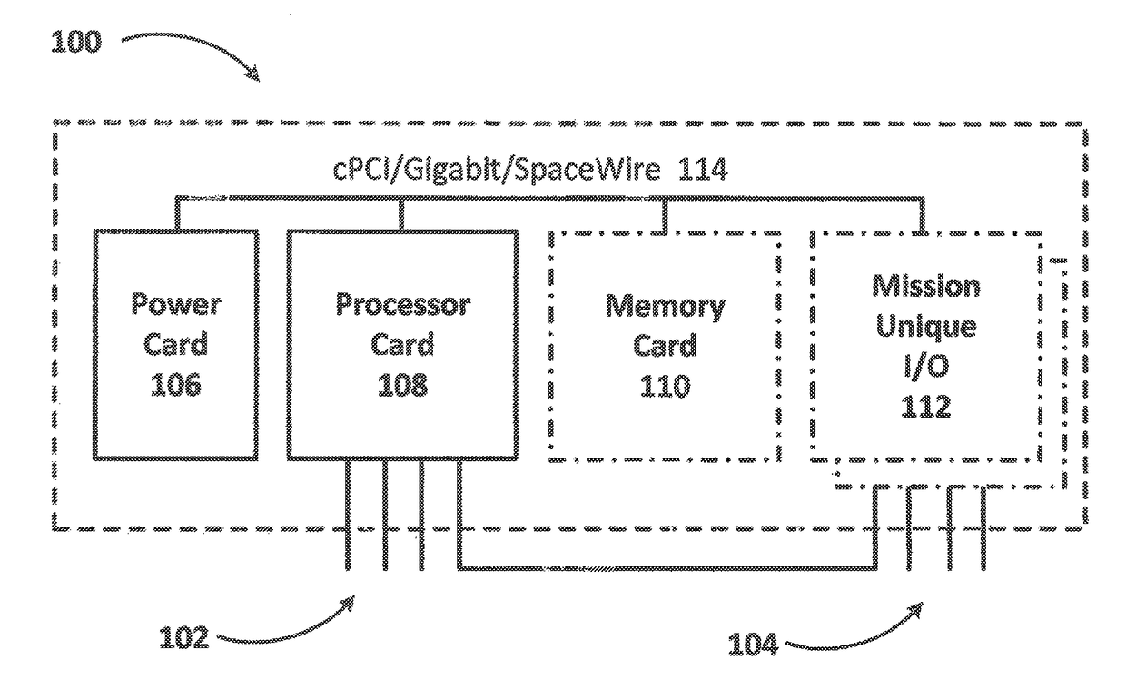
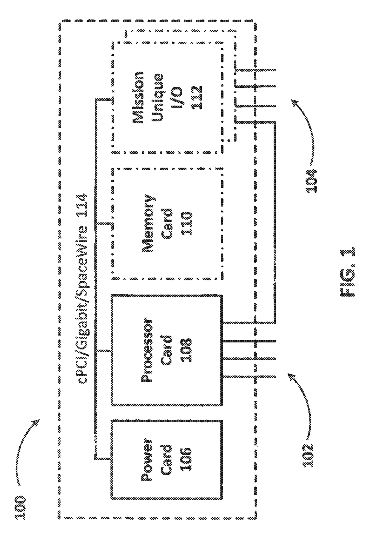
[0018]FIG. 1 illustrates a card level architectural block diagram of a processing system generally indicated by numeral 100 designed for use in space missions. The processing system 100 is designed around a processor card 108 which is based on newly developed FPGA technology and is configured to provide advanced parallel processing capabilities as well as software mitigation. The processor board 108 is designed to provide one to two orders of magnitude improvements in on-board computing power while lowering relative power consumption and cost as compared to currently available space based processors. The processor card 108 includes a number of flash memory devices which may be electrically reprogrammed while in the system to provide on the fly reconfiguration capabilities required by space missions. The processor card 108 is supported by a power card 106, an optional memory card 110, and an optional mission unique input / output (I / O) card 112. To tie the power, processor, memory and ...


PUM


Abstract

A low power voltage control circuit for use in space missions includes a switching device coupled between an input voltage and an output voltage. The switching device includes a control input coupled to an enable signal, wherein the control input is configured to selectively turn the output voltage on or off based at least in part on the enable signal. A current monitoring circuit is coupled to the output voltage and configured to produce a trip signal, wherein the trip signal is active when a load current flowing through the switching device is determined to exceed a predetermined threshold and is inactive otherwise. The power voltage control circuit is constructed of space qualified components.

Description

[0001]This application claims priority to Provisional Application No. 61 / 790,944, entitled “SPACECUBE 2.0 SYSTEM.” filed Mar. 15, 2013. The content of this application is hereby incorporated by reference.[0002]The invention described herein was made by an employee of the United States Government and may be manufactured and used by or for the Government of the United States of America for governmental purposes without the payment of any royalties thereon or therefor.FIELD[0003]The aspects of the present disclosure relate generally to space-based processing systems, and in particular, to low power voltage control circuits.BACKGROUND[0004]Many space-based science missions require “next generation” on-board processing capabilities to meet the specified goals of each mission. These missions use advanced instrumentation systems, such as laser altimeter, radar, lidar, and hyper-spectral instruments, which all require advanced on-board processing capabilities to facilitate the timely conver...

Claims


Application Information

Patent Timeline
Patent Type & Authority Patents(United States)
IPC IPC(8): H02J3/14H02J1/00H02H3/087
CPCH02J1/00H02H3/087H05K1/181H05K3/4644H05K2201/09409H05K2201/10189H05K2201/10409H05K2201/10446H05K2201/10545H05K2201/10568H05K2201/10628H05K1/113Y02P70/50G06F1/185G06F1/189H05K1/0298H05K1/115
Inventor PETRICK, DAVID J.
Owner NASA
Features
  • R&D
  • Intellectual Property
  • Life Sciences
  • Materials
  • Tech Scout
  • Unparalleled Data Quality
  • Higher Quality Content
  • 60% Fewer Hallucinations
Learn More