
Method of measuring vertical beam profile in an ion implantation system having a vertical beam angle device

a technology of ion implantation system and vertical beam, which is applied in the field of system method of measuring vertical beam profile in scanned beam ion implantation apparatus, can solve the problems of not having the capability of measuring vertical profile or position, and achieve the advantages of achieving vertical beam profile, disadvantageous consequences, and very precise tilt motion

Active Publication Date: 2017-07-18
AXCELIS TECHNOLOGIES
View PDF2 Cites 4 Cited by
  • Summary
  • Abstract
  • Description
  • Claims
  • Application Information

AI Technical Summary

Benefits of technology

This solution enables more accurate and efficient ion implantation by maximizing beam utilization, improving throughput and energy efficiency, and ensuring uniform doping across semiconductor substrates.

Problems solved by technology

Ion implantation systems, such as the so-called “Optima XE” system manufactured by Axcelis Technologies, Inc. or Beverly, Mass., do not have a capability of measuring a vertical profile or position of an ion beam.

Method used


Image

  • Method of measuring vertical beam profile in an ion implantation system having a vertical beam angle device
  • Method of measuring vertical beam profile in an ion implantation system having a vertical beam angle device
  • Method of measuring vertical beam profile in an ion implantation system having a vertical beam angle device

Examples


Embodiment Construction

[0022]One or more aspects of the present invention are described with reference to the drawings, wherein like reference numerals are generally utilized to refer to like elements throughout, and wherein the various structures are not necessarily drawn to scale. In the following description, for purposes of explanation, numerous specific details are set forth in order to provide a thorough understanding of one or more aspects of the present invention. It may be evident, however, to one skilled in the art that one or more aspects of the present invention may be practiced with a lesser degree of these specific details. In other instances, well-known structures and devices are shown in block diagram form in order to facilitate describing one or more aspects of the present invention.

[0023]In semiconductor fabrication processing, semiconductor wafers or workpieces are implanted with charged particles or ions. The ions exhibit desired electrical characteristics due to their net positive or ...


PUM


Abstract

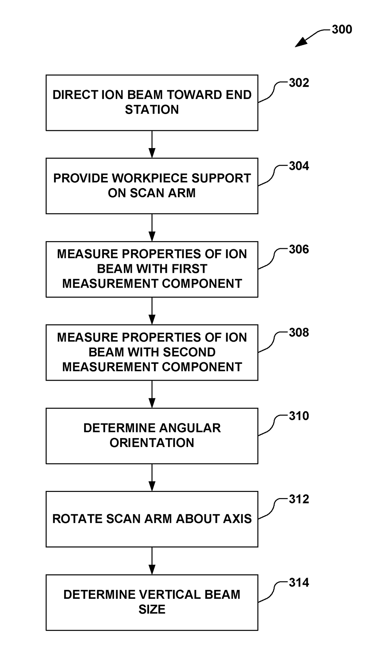
An ion implantation system measurement system has a scan arm that rotates about an axis and a workpiece support to translate a workpiece through the ion beam. A first measurement component downstream of the scan arm provides a first signal from the ion beam. A second measurement component with a mask is coupled to the scan arm to provide a second signal from the ion beam with the rotation of the scan arm. The mask permits varying amounts of the ion radiation from the ion beam to enter a Faraday cup based on an angular orientation between the mask and the ion beam. A blocking plate selectively blocks the ion beam to the first faraday based on the rotation of the scan arm. A controller determines an angle and vertical size of the ion beam based on the first signal, second signal, and orientation between the mask and ion beam as the second measurement component rotates.

Description

REFERENCE TO RELATED APPLICATION[0001]This application claims priority to and the benefit of U.S. Provisional Application Ser. No. 62 / 096,928 which was filed Dec. 26, 2014, entitled “METHOD OF MEASURING VERTICAL BEAM PROFILE IN AN ION IMPLANTATION SYSTEM HAVING A VERTICAL BEAM ANGLE DEVICE”, the entirety of which is hereby incorporated by reference as if fully set forth herein.FIELD OF THE INVENTION[0002]The present invention relates generally to ion implantation systems, and more specifically to a system method for measuring a vertical ion beam profile in a scanned beam ion implantation apparatus having a device for measuring vertical beam angle.BACKGROUND OF THE INVENTION[0003]Ion implantation systems are mechanisms utilized to dope semiconductor substrates with dopants or impurities in integrated circuit manufacturing. In such systems, a dopant material is ionized and an ion beam is generated therefrom. The ion beam is directed at the surface of a semiconductor wafer in order to ...

Claims


Application Information

Patent Timeline
Patent Type & Authority Patents(United States)
IPC IPC(8): H01J37/36H01J37/30H01J37/317H01J37/304
CPCH01J37/3045H01J37/304H01J37/3171H01J2237/244H01J2237/24405H01J2237/24542
Inventor SATOH, SHU
Owner AXCELIS TECHNOLOGIES
Learn More