
Lost access point power save mode for WiFi devices

a power saving mode and wifi technology, applied in the field of radiofrequency (rf) communication devices and systems, can solve the problems of consuming a non-negligible amount of power, undue draining of a battery pack,

Active Publication Date: 2017-07-18
NETGEAR INC
View PDF8 Cites 14 Cited by
  • Summary
  • Abstract
  • Description
  • Claims
  • Application Information

AI Technical Summary

Benefits of technology

[0013]The invention addresses the above and other needs by providing a methods, devices and systems that further decrease power consumption in the low-power wireless devices and systems.
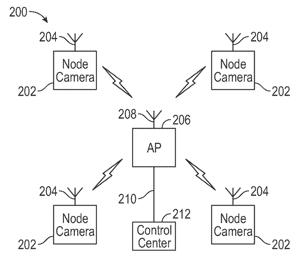
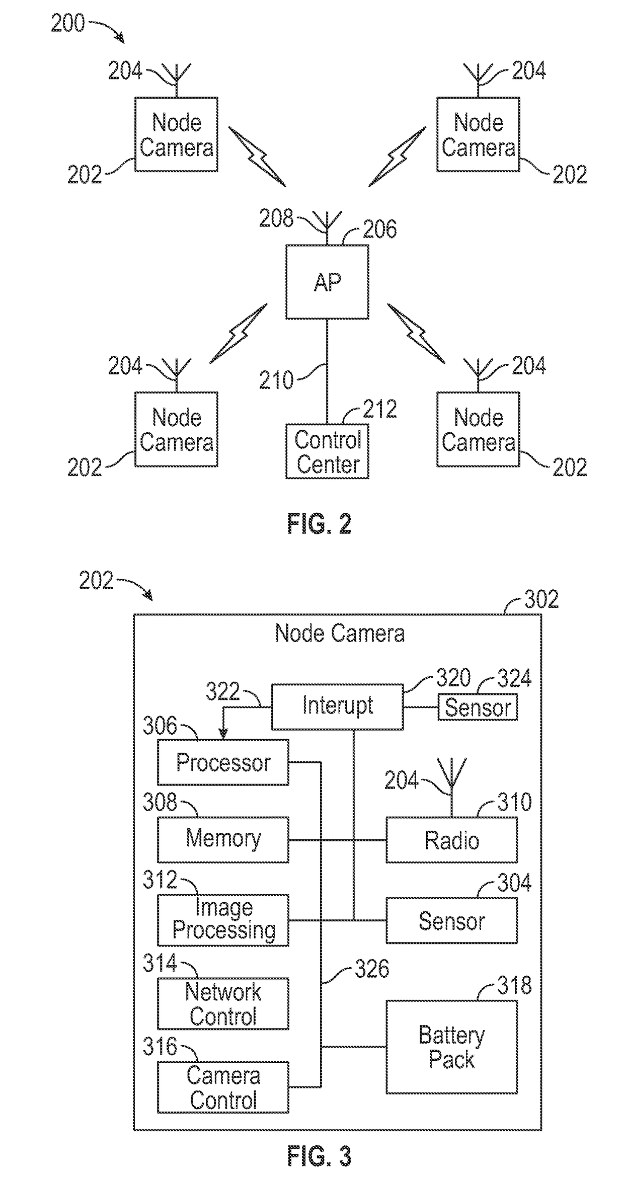
[0014]In one embodiment of the invention, a wireless camera system and network is provided, which includes: a plurality of battery-powered, wireless node cameras, each node camera comprising an image sensor for capturing image data, a radio unit for performing wireless communications, at least one processing unit for controlling the image sensor and radio unit, and at least one battery; and an access point configured to communicate wirelessly with each of the node cameras, and further configured to communicate with a control center that communicatively couples the access point to a computer network, wherein the at least one processing unit in each node camera, includes: a host processing unit; and a sleep mode unit coupled to the host processing unit and the radio unit configured to control a sleep time of the host processing unit and the radio unit, wherein if the radio unit does not receive a signal from the access point that associates a respective node camera with the access point after a predetermined number of attempts, the sleep mode unit increases the sleep time of the host processing unit and the radio unit after each set of one or more subsequent failed attempts by the respective node camera to associate with the access point.
[0015]In another embodiment, the invention provides a battery-powered, wireless camera that includes: an image sensor for capturing image data; a radio unit for performing wireless communications with at least one external device; at least one battery for supplying power to the wireless camera; and at least one processing unit for controlling the radio unit, wherein the at least one processing unit, includes: a host processing unit; and a sleep mode unit, coupled to the host processing unit and the radio unit, configured to control a sleep time of the host processing unit and the radio unit, wherein if the radio unit does not receive a signal from the access point that associates the wireless camera with the access point after a predetermined number of attempts, the sleep mode unit increases the sleep time of the host processing unit and the radio unit after each set of one or more subsequent failed attempts by the wireless camera to associate with the access point.
[0016]In another embodiment, the invention is directed to a wireless communication device, including: a radio unit configured to provide two-way wireless communications; a host processing unit; and a sleep mode unit, coupled to the host processing unit and the radio unit, configured to control a sleep time of the host processing unit and the radio unit, wherein if the radio unit does not receive a signal from the access point that associates the wireless communication device with the access point after a predetermined number of attempts, the sleep mode unit increases the sleep time of the host processing unit and the radio unit after each set of one or more subsequent failed attempts by the wireless communication device to associate with the access point.
[0017]In yet a further embodiment, the invention provide a method for associating a wireless communication device with an access point, the method including: if the wireless communication device does not receive a signal from the access point that associates the wireless communication device with the access point after a predetermined number of tries, increasing a sleep time of the wireless communication device after each set of one or more subsequent failed attempts by the wireless communication device to associate with the access point.

Problems solved by technology

Even in this sleep mode, however, the RF transceiver, comprising a WiFi signal processing unit and RF front and back end units, as described above, consumes a non-negligible amount of power, which over time will unduly drain a battery pack.
Thus, in this example, even during sleep mode (a.k.a., “idle mode”), a conventional low-power WiFi device may still have a total power consumption of 224 μW (excluding any additional power lost due to power supply inefficiencies).
This power consumption is a drain on the battery pack of the WiFi device.
In addition to power consumption by the RF transceiver, typical WiFi devices must power on a host processor that controls the RF transceiver and performs necessary network and application processing functions (e.g., functions above the MAC layer) each time the RF transceiver transmits or receives a signal.
The powering on of the host processor in this fashion results in significant power consumption by the WiFi device.

Method used


Image

  • Lost access point power save mode for WiFi devices
  • Lost access point power save mode for WiFi devices
  • Lost access point power save mode for WiFi devices

Examples


Embodiment Construction

[0030]In the following description of exemplary embodiments, reference is made to the accompanying drawings which form a part hereof, and in which it is shown by way of illustration of specific exemplary embodiments in which the invention may be practiced. It is to be understood that other embodiments may be utilized and changes may be made without departing from the scope of the invention. Various embodiments of the invention are described below in the context of a battery-powered, WiFi camera network, which is one example of a low-power, wireless communication application. Although various embodiments and features of the invention are described below in the context of a battery-powered, wireless camera network, it will be appreciated by those of ordinary skill in the art that various features and advantages of the invention can be applied to other types of wireless communication devices, systems or networks in which low power operation is desired.

[0031]FIG. 2 illustrates a wireles...


PUM


Abstract

The invention is directed to a wireless communication device that includes: a radio unit configured to provide two-way wireless communications; a host processing unit; and a sleep mode unit, coupled to the host processing unit and the radio unit, configured to control a sleep time of the host processing unit and the radio unit, wherein if the radio unit does not receive a signal from the access point that associates the wireless communication device with the access point, the sleep unit increases the sleep time of the host processing unit and the radio unit after each set of one or more failed attempts by the wireless communication device to associate with the access point.

Description

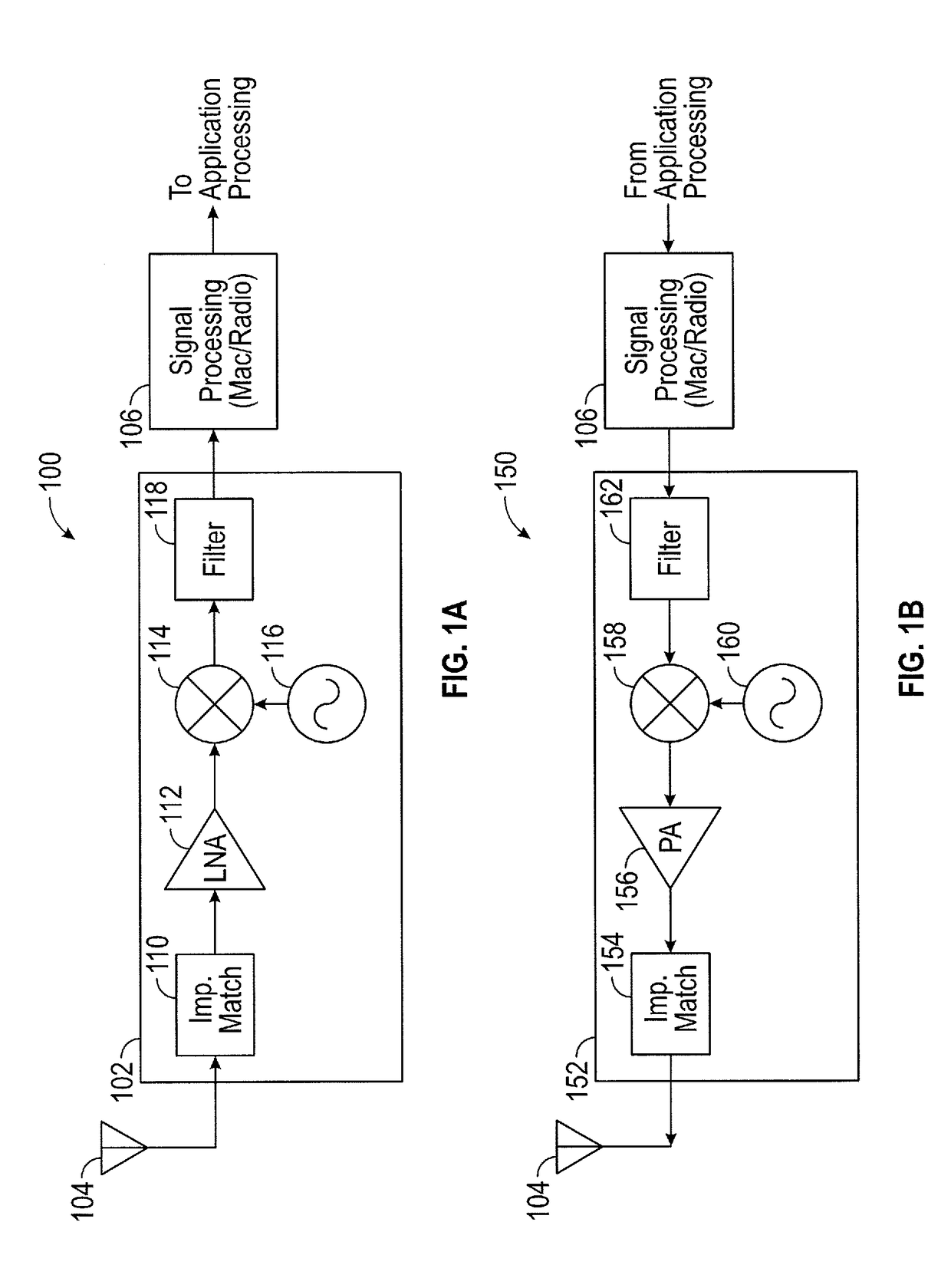
FIELD OF THE INVENTION[0001]The invention is related generally to radio-frequency (RF) communication devices and systems and, more particularly, to a method and apparatus for conserving power used by RF devices and systems.BACKGROUND OF THE INVENTION[0002]RF devices and systems typically include one or more RF transceivers for transmitting and receiving wireless signals. FIGS. 1A and 1B illustrate block diagrams of conventional receiver and transmitter circuits of an RF transceiver, respectively. As shown in FIG. 1A, a RF receiver circuit 100 include a RF front end unit 102, coupled to at least one antenna 104, and a signal processing unit 106 coupled to the RF front end unit 102. The RF front end unit 102 includes an impedance matching circuit 110, a low-noise amplifier (LNA) 112, a mixer 114, a local oscillator 116 and a band-pass filter 118. The impedance matching circuit 110 matches the input impedance of the receiver 100 with the impedance of the antenna so that maximum power o...

Claims


Application Information

Patent Timeline
Patent Type & Authority Patents(United States)
IPC IPC(8): H04B1/16H04W52/02
CPCH04W52/0203H04W52/0216H04W52/0219H04W52/0229H04W52/0274Y02D30/70
Inventor SKEOCH, STEVEMCGILL, CHRIS
Owner NETGEAR INC
Learn More