
Audible noise reduction method for multiple LED channel systems

a technology of led channel system and audible noise reduction, which is applied in the direction of lighting apparatus, electrical equipment, light sources, etc., can solve the problems of high pwm switching frequency switching power loss, led color shift, undesirable side effects

Active Publication Date: 2017-07-25
INTEGRATED SILICON SOLUTION
View PDF9 Cites 25 Cited by
  • Summary
  • Abstract
  • Description
  • Claims
  • Application Information

AI Technical Summary

Benefits of technology

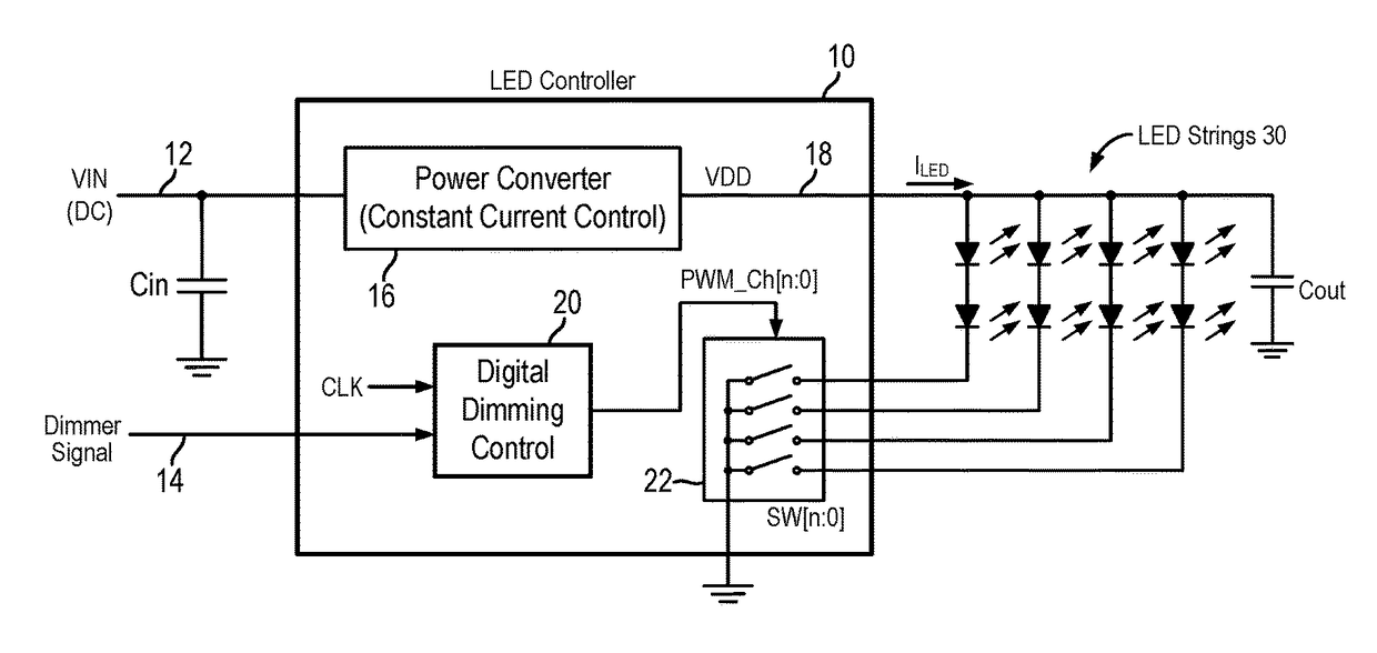
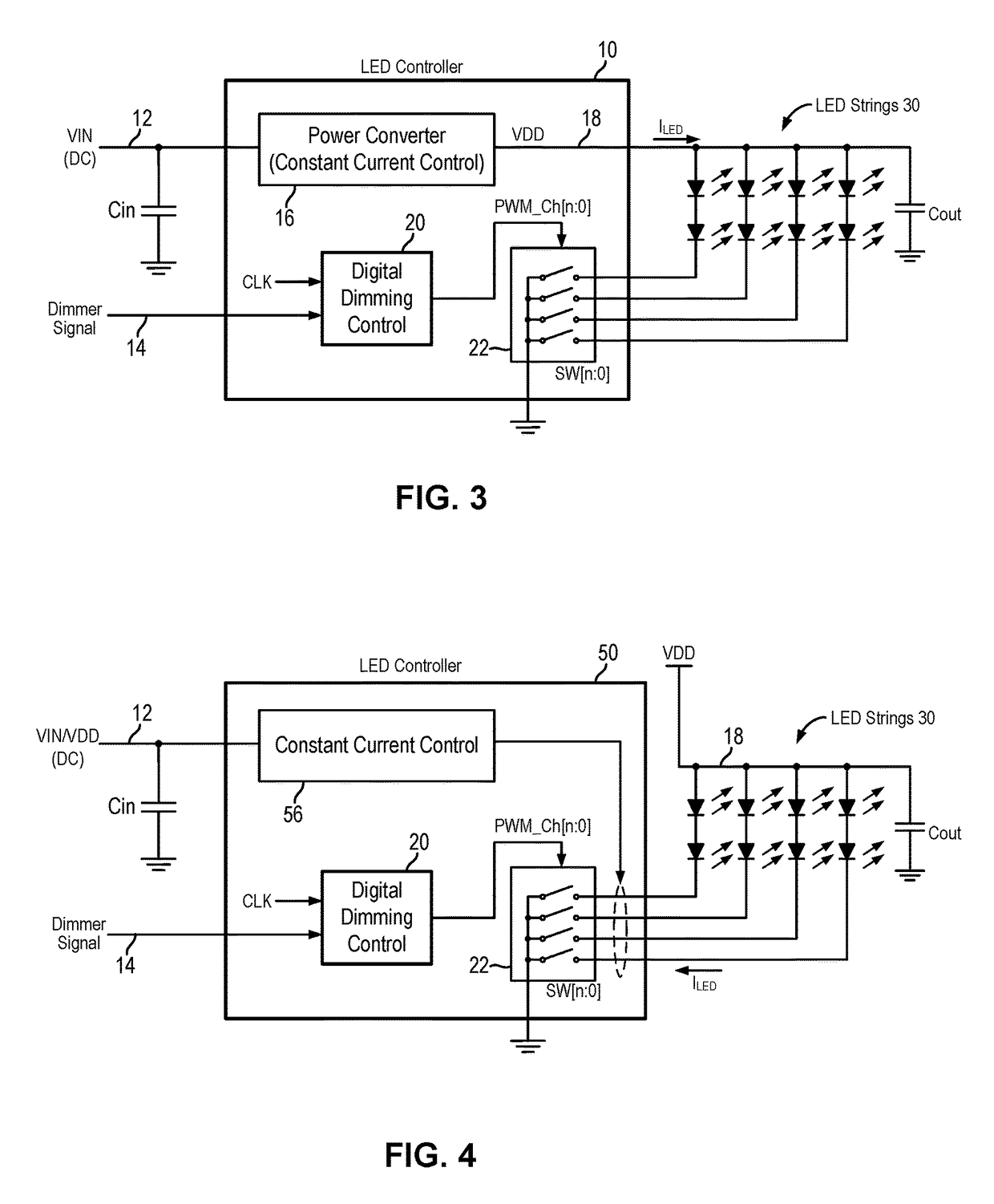
The patent text discusses the issue of audible noise caused by LED dimming using PWM signals. The technical solution proposed is to use a power supply voltage isolation and an output capacitor to eliminate voltage ripple at the input capacitor and absorb power ripple across the LEDs. This reduces the noise and improves the overall performance of LED lighting applications.

Problems solved by technology

Reducing the LED current to reduce LED brightness to achieve dimming function also unwantedly shifts the LED color, which is undesirable.
Although, higher frequencies can be used, high PWM switching frequency will have higher switching power loss, as well as more harmonic electromagnetic interference (EMI) emission into frequency range which may interfere with adjacent RF circuit operation.
However, in the typical applications, implementing LED dimming by PWM switching sometimes leads to undesirable side effects.
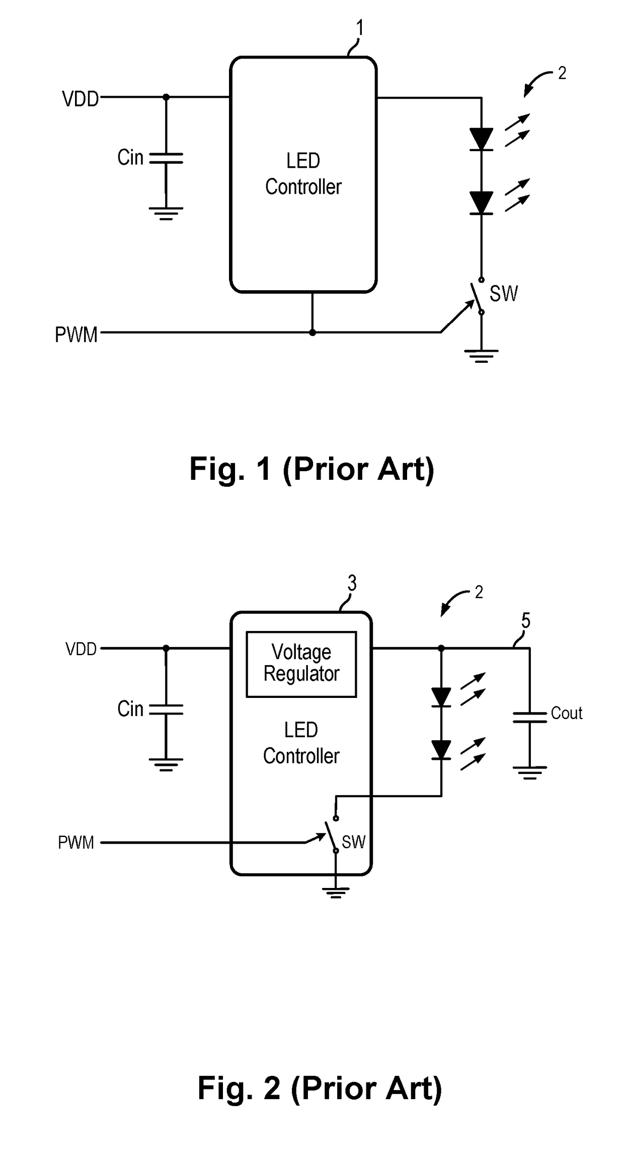
With sufficiently large LED current being turned on or off, large voltage ripple can be developed on VDD power rail to cause the input capacitor to resonate at the PWM frequency, thereby generating audible noise since the PWM frequency is within the audible frequency range of human hearing.
However, it is often not possible to implement these solutions as they require larger PCB layout and dual side surface-mount manufacturing adds component cost and production cost.
However, these capacitors are more expensive than ceramic capacitors and therefore increases the component cost.
When driving large LED current, the capacitance of the output capacitor Cout has to be increased proportionally, otherwise the voltage on Cout itself will generate ripple, becoming another audible noise source.
When the LED current is large, the conduction loss incurred in switch SW can be large, causing system power loss.
When multiple LED strings are used, the LED current becomes very large, which can cause large ripple on the power rail.
Thus, the audible noise issue caused by the LED dimming function becomes even more serious.
Although shifting the PWM frequency out of the human audible range can completely obviate the audible noise issue in LED dimming, this method is sometimes not desirable due to electromagnetic interference (EMI) concerns when the PWM frequency is shifted to a high frequency.
Faster PWM frequency will also increase operation switching loss, reducing system power efficiency.
Also, ripples on the VDD power rail still exists, which may affect other devices that are sharing the same power rail.
In addition, for high contrast ratio applications, e.g., 5,000:1, the LED driver circuit may not be able to switch fast enough for such a high frequency operation.
Although clock skewing can be used to alleviate the EMI concern, clock skewing has limited applications due to timing constraints.

Method used


Image

  • Audible noise reduction method for multiple LED channel systems
  • Audible noise reduction method for multiple LED channel systems
  • Audible noise reduction method for multiple LED channel systems

Examples


Embodiment Construction

[0024]The invention can be implemented in numerous ways, including as a process; an apparatus; a system; and / or a composition of matter. In this specification, these implementations, or any other form that the invention may take, may be referred to as techniques. In general, the order of the steps of disclosed processes may be altered within the scope of the invention.

[0025]A detailed description of one or more embodiments of the invention is provided below along with accompanying figures that illustrate the principles of the invention. The invention is described in connection with such embodiments, but the invention is not limited to any embodiment. The scope of the invention is limited only by the claims and the invention encompasses numerous alternatives, modifications and equivalents. Numerous specific details are set forth in the following description in order to provide a thorough understanding of the invention. These details are provided for the purpose of example and the inv...


PUM


Abstract

An LED controller for a multiple LED channel system using PWM method for LED dimming function incorporates a digital dimming control circuit to generate the PWM signals for driving the LED channels to spread out or cancel out the power supply transients generated by the LED transient current during PWM modulation for dimming operation. The digital dimming control circuit implements an audible noise reduction method whereby the active period of the PWM signals for some of the LED channels are shifted within the switching cycle to align at least some of the rising signal edges with some of the falling signal edges so as to cancel out the voltage transients on the LED power rails generated at the signal transitions. Furthermore, the rising and falling signal edges that are not lined up are spread out through the PWM switching cycle so that the power supply transients are spread out.

Description

BACKGROUND OF THE INVENTION[0001]Incandescent light bulbs are quickly being replaced by light-emitting diodes (LEDs), in particular, in automotive market. This is because LED technology provides greatly improved energy efficiency, better reliability, lowered cost and smaller form factor compared with incandescent light bulbs. LEDs are typically packaged as surface-mount device (SMD) which allows for high volume, low cost printed circuit board (PCB) manufacturing along with ever advanced semiconductor technology, further reducing production cost. LED lighting generates less heat which further reduces environment cooling requirement and cost. With LED integration into the automotive market, fuel efficiency can be improved for longer cruising range and lower fuel cost.[0002]Many LED applications require a dimming function. One method of achieving LED dimming function is to adjust the LED forward current. However, it is well known that LED's light spectrum is also dependent on LED's for...

Claims


Application Information

Patent Timeline
IPC IPC(8): H05B33/08H05B44/00
CPCH05B33/0815H05B33/0827H05B33/0845H05B45/10H05B45/46H05B45/37H05B45/375H05B45/38H05B45/3725H05B45/395
Inventor YAO, CHUNGTING
Owner INTEGRATED SILICON SOLUTION
Learn More