
Apparatus and method for estimating parameter of secondary battery

a secondary battery and parameter estimation technology, applied in secondary cell servicing/maintenance, cell components, instruments, etc., can solve the problems of complex calculation, limited satisfaction of all industrial performance standards with only one cathode material, and inability to measure the ocv of a secondary battery during charging or discharging of the secondary battery, etc., to achieve accurate estimation, improve reliability of estimated parameters, and reliable estimation of ocv and/or soc

Active Publication Date: 2017-08-01
LG ENERGY SOLUTION LTD
View PDF34 Cites 1 Cited by
  • Summary
  • Abstract
  • Description
  • Claims
  • Application Information

AI Technical Summary

Benefits of technology

[0045]According to the present disclosure, an open-circuit voltage (OCV) and / or a state of charge (SOC) of a secondary battery may be reliably estimated during dynamic charging of the secondary battery. Particularly, for a secondary battery including a blended cathode material showing a unique voltage change pattern, reliable estimation of an OCV and / or an SOC may be achieved as well. Also, even if polarization on an electrode of a secondary battery is accumulated, an OCV and / or an SOC may be estimated accurately. Because the OCV and / or the SOC is estimated using current-voltage data measured in a state of reduced polarization accumulation on the secondary battery, reliability of the estimated parameter may be improved.

Problems solved by technology

However, there is still a limitation in satisfying all the industrial performance standards with only one cathode material.
However, it is impossible to measure an OCV of a secondary battery during charging or discharging of the secondary battery.
However, the former method has a disadvantage of requiring a complicated calculation, and the latter method has a drawback of reduced accuracy when applied during charging or discharging of a secondary battery under a dynamic condition.

Method used


Image

  • Apparatus and method for estimating parameter of secondary battery
  • Apparatus and method for estimating parameter of secondary battery
  • Apparatus and method for estimating parameter of secondary battery

Examples


experiment example 1

Fabrication of Secondary Battery

[0189]A secondary battery including a single cathode material was fabricated in accordance with the following specification.[0190]Cathode material: LiCo1 / 3Ni1 / 3M1 / 3O2 [0191]Anode material: Graphite[0192]Electrolyte: LiPF6 added to a mixed solvent of EC(Ethyl Carbonate) / DMC(DiMethyl Carbonate) / EMC(EthylMethyl Carbonate) mixed at a weight ratio of 3:4:3[0193]Separator: Porous polyolefin film coated with inorganic particles on both surfaces[0194]Casing: Pouch casing

[0195]Charge / Discharge Experiment

[0196]FIG. 5 is a graph illustrating measurements of a charging / discharging current profile and a voltage change of a secondary battery.

[0197]The charging / discharging current profile simulates a driving pattern in Los Angeles used as vehicle testing standards in the U.S. hybrid vehicle industry under the assumption that the secondary battery is used in a hybrid vehicle.

[0198]In the charging / discharging current profile, a section A is a period during which the s...

experiment example 2

Fabrication of Secondary Battery

[0200]A secondary battery including a blended cathode material was fabricated in accordance with the following specification.[0201]Cathode material: Blended cathode material of LiCo1 / 3Ni1 / 3Mn1 / 3O2 and LiFePO4 at a weight ratio of 7:3[0202]Anode material: Graphite[0203]Electrolyte: LiPF6 added to a mixed solvent of EC / DMC / EMC mixed at a weight ratio of 3:4:3[0204]Separator: Porous polyolefin film coated with inorganic particles on both surfaces[0205]Casing: Pouch casing

[0206]Observation of Characteristics of Secondary Battery

[0207]During charging of the secondary battery, lithium ions deintercalated from the cathode material are intercalated into the anode material. However, LiCo1 / 3Ni1 / 3Mn1 / 3O2 and LiFePO4 differ in concentration at which lithium ions are deintercalated as a charging voltage of the secondary battery changes. That is, for a low voltage charging period, lithium ions are deintercalated from LiFePO4, and for a high voltage charging period,...

experiment example 3

[0223]In this experiment, a difference between an estimated SOC of the secondary battery fabricated in Experiment example 1 using the present disclosure and an actually measured SOC of the secondary battery was measured.

[0224]FIG. 12 is a graph illustrating two current-voltage data (extrapolation data) used when calculating a linear approximation equation, indicated on a current-voltage profile. One is data measured when a magnitude of a charging current decreases from a peak value to 15 A, and the other is data measured when a magnitude of an electric current decreases from a peak value to 5 A. The current-voltage data constituting the extrapolation data is all data measured when the magnitude of the charging current decreases to ⅓ (20 ampere) or less, based on the peak value (65 ampere).

[0225]FIG. 13 is a graph illustrating a concept of estimating a Y intercept as an OCV of a secondary battery when calculating a linear approximation equation using two current-voltage data.

[0226]FI...


PUM

PropertyMeasurementUnit
charging currentaaaaaaaaaa
timeaaaaaaaaaa

Abstract

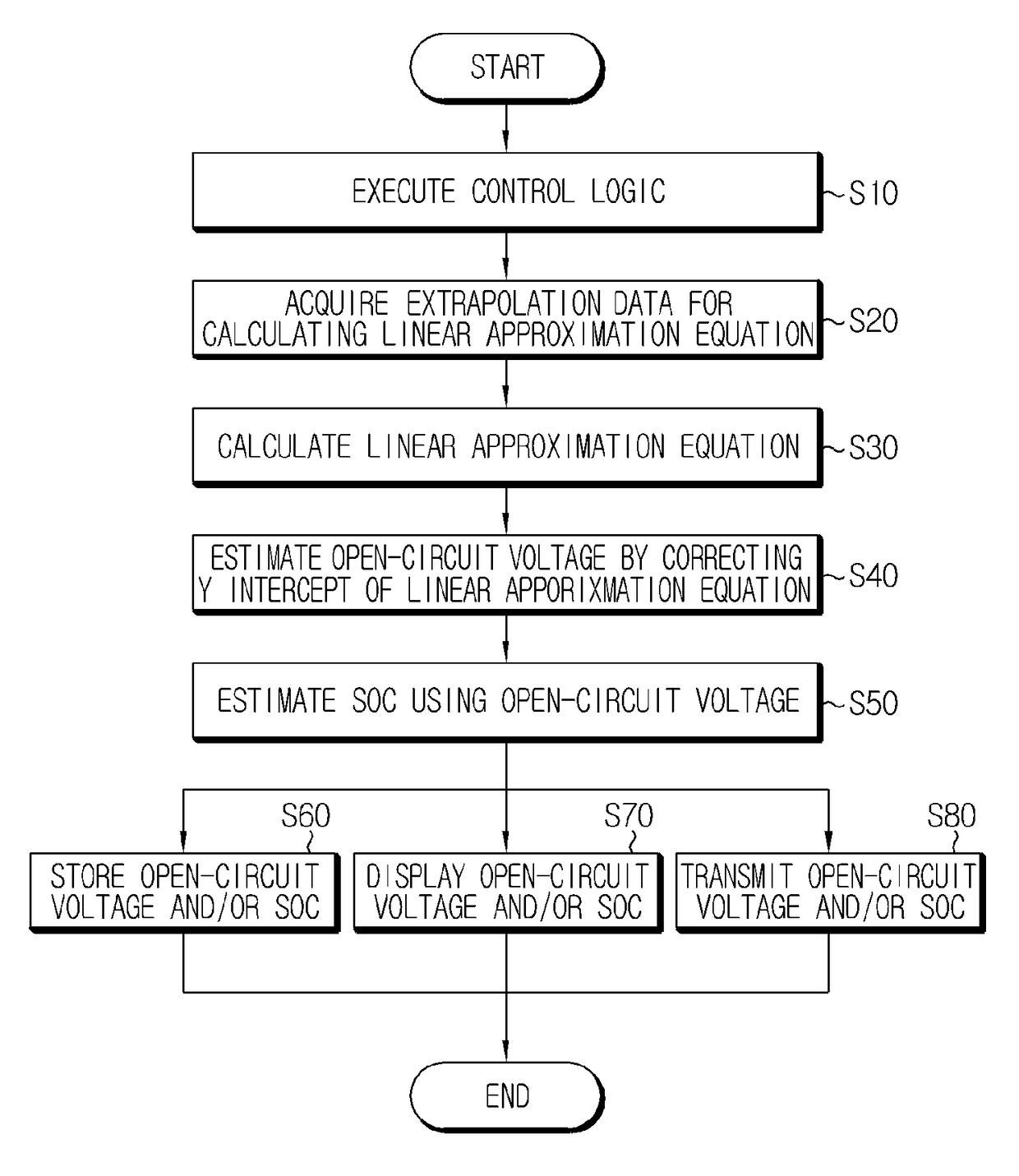
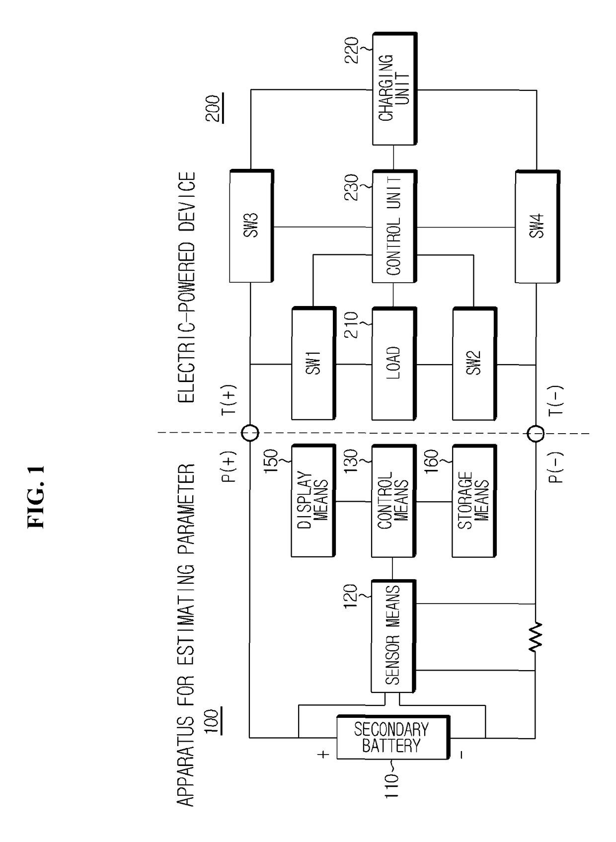
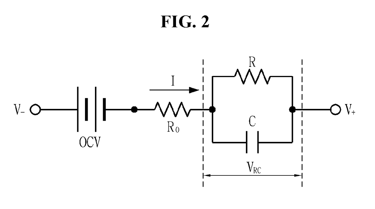
Disclosed is an apparatus and method for estimating a parameter of a secondary battery. The apparatus according to the present disclosure includes a sensor means configured to measure a plurality of current-voltage data while a charging current decreases when a secondary battery is charged in such a pattern that the charging current increases to a peak value and then decreases, and a control means configured to receive an input of the plurality of current-voltage data from the sensor means, calculate a linear approximation equation representing a correlation between a current and a voltage from the plurality of current-voltage data, estimate an open-circuit voltage (OCV) of the secondary battery by reflecting a polarization voltage of the secondary battery quantified through a resistor-capacitor (RC) circuit on a Y intercept of the linear approximation equation, and estimate a state of charge (SOC) of the secondary battery from the estimated OCV.

Description

CROSS-REFERENCE TO RELATED APPLICATION[0001]The present application is a continuation of International Application No. PCT / KR2013 / 011175 filed on Dec. 4, 2013, which claims priority to Korean Patent Application No. 10-2012-0139776 filed in the Republic of Korea on Dec. 4, 2012, and Korean Patent Application No. 10-2013-0149690 filed in the Republic of Korea on Dec. 4, 2013, the disclosures of which are incorporated herein by reference.TECHNICAL FIELD[0002]The present disclosure relates to an apparatus and method for estimating an electrochemical parameter of a secondary battery changing during charging or discharging of the secondary battery such as an open-circuit voltage (OCV) or a state of charge (SOC) of the secondary battery.BACKGROUND ART[0003]A battery is a device that produces electrical energy through electrochemical oxidation and reduction reactions, and has a wide range of various applications. For example, application of a battery is gradually expanding to a power source...

Claims


Application Information

Patent Timeline
Patent Type & Authority Patents(United States)
IPC IPC(8): H01M10/44G01R31/36H01M10/46B60L11/18H01M10/48G01R31/00H01M4/505H01M4/525H01M4/58
CPCG01R31/3624B60L11/1861G01R31/3651G01R31/007G01R31/3662H01M10/48B60L2240/547B60L2240/549B60L2260/44B60L58/12G01R31/3842G01R31/367G01R31/389Y02T10/70Y02E60/10G01R19/165G01R31/36
Inventor JOE, WON-TAE
Owner LG ENERGY SOLUTION LTD
Learn More