
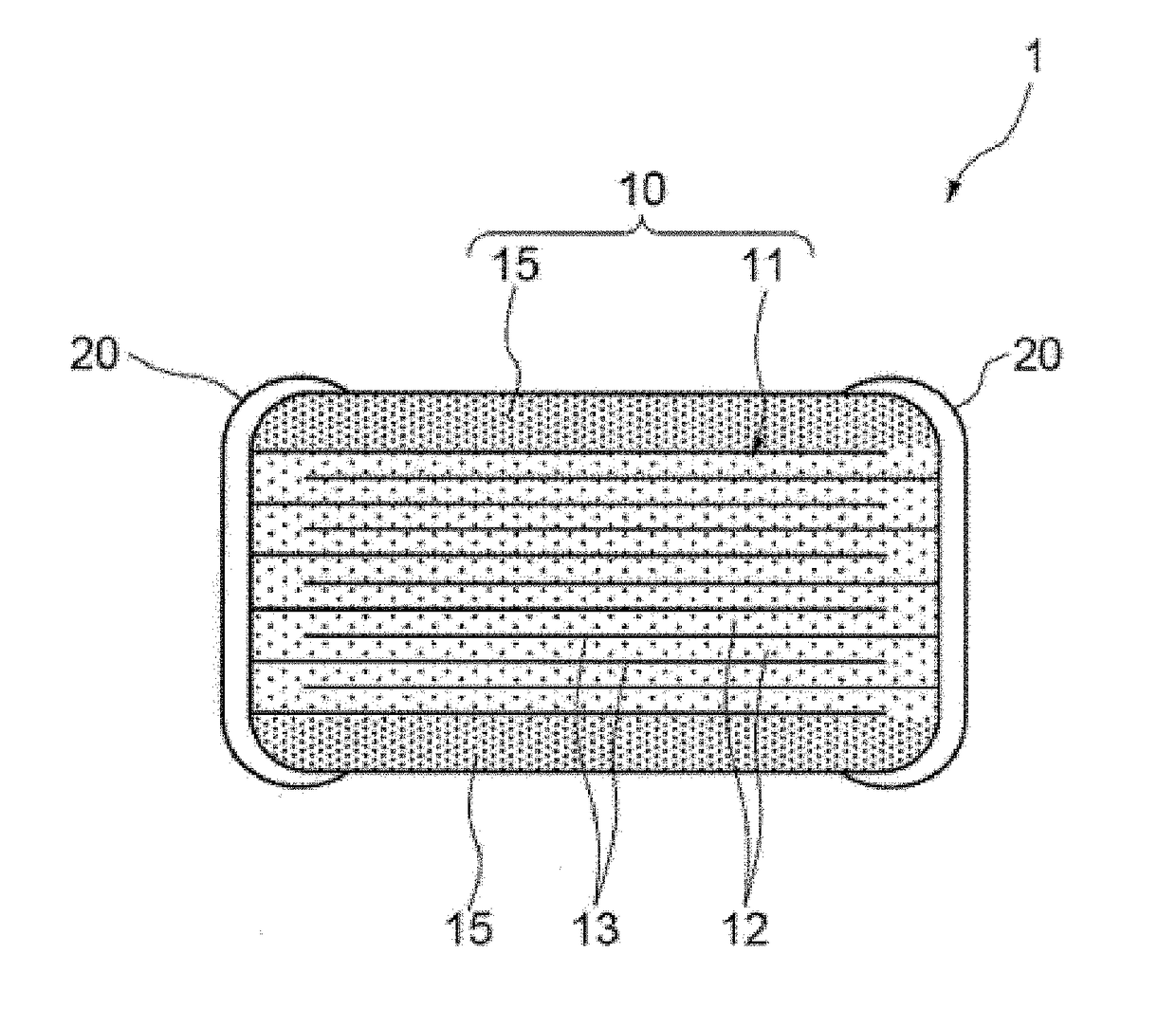
Multilayer ceramic capacitor

a multi-layer ceramic capacitor and ceramic capacitor technology, applied in the direction of fixed capacitors, stacked capacitors, fixed capacitor details, etc., can solve the problems of service life cannot be improved sufficiently, and bias characteristics of multi-layer ceramic capacitors as a whole to drop, so as to improve service life characteristics and service life characteristics to drop

Active Publication Date: 2017-08-01
TAIYO YUDEN KK
View PDF8 Cites 1 Cited by
  • Summary
  • Abstract
  • Description
  • Claims
  • Application Information

AI Technical Summary

Benefits of technology

The invention aims to improve the service life and bias characteristics of multilayer ceramic capacitors that have a thickness of 0.8 μm or less. The inventors found that a fluctuating distribution of additive elements in the ceramic grain caused more oxygen defects in low concentration areas, which led to a drop in service life. To address this issue, the inventors developed a new method that can reduce oxygen defects and improve the overall performance of the multilayer ceramic capacitor.

Problems solved by technology

To be specific, a fluctuating distribution of additive elements in the ceramic grain leads to more oxygen defects in low concentration areas, which in turn causes the service life characteristics to drop.
If a location exists where the donor constituents are less abundant, the amount of oxygen defects increases at that location and consequently the service life cannot be improved sufficiently owing to the donor constituents.
In addition, it was also found that, in areas where these donor constituents are highly concentrated, the bias characteristics drop and as a result the bias characteristics of the multilayer ceramic capacitor as a whole also drop.

Method used


Image

  • Multilayer ceramic capacitor
  • Multilayer ceramic capacitor
  • Multilayer ceramic capacitor

Examples


example 1

[0073]Mo was used as donor element X. Hexaammonium heptamolybdate tetrahydrate was dissolved in ion exchange water and, after adding a dispersant, the resulting aqueous solution was made into a slurry with BaCO3 (30 m2 / g) and TiO2 (50 m2 / g) added to a Ba / Ti mol ratio of 1, and then the slurry was mixed and dispersed using a bead mill.

[0074]For this slurry, 0.05 mol of Mo was added in equivalent MoO3 quantity relative to 100 mol of the barium titanate. The slurry was dried to remove the water, and then calcinated at 900° C., to synthesize a Mo-containing barium titanate with an average grain size of 80 nm as obtained from SEM photographs.

[0075]Next, additive materials were added at ratios of 0.5 mol for Ho2O3, 0.1 mol for MnCO3, 0.1 mol for V2O5, and 1.0 mol for SiO2, relative to 100 mol of the Mo-containing barium titanate, and BaCO3 or TiO2 was also added so that the Ba / Ti mol ratio (mol ratio of Ba and Ti in the total of barium titanate containing Mo solid solution and BaCO3 or Ti...

example 2

[0088]A multilayer ceramic capacitor was produced in the same manner as in Example 1, except that MoO3 with a specific surface area of 5 m2 / g was used as the Mo material and 0.2 mol of Mo was added in equivalent MoO3 quantity.

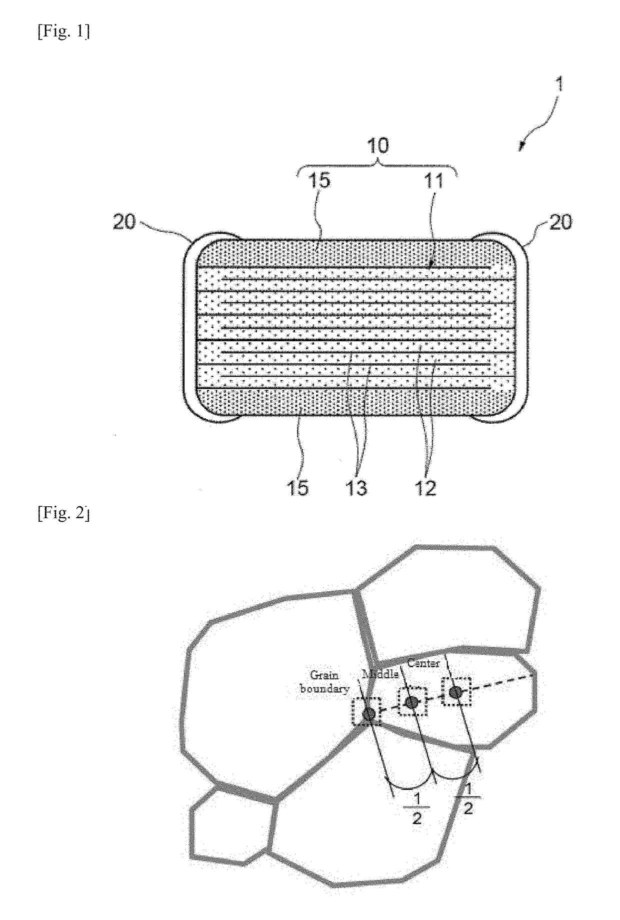
[0089]When the peak intensity ratio was measured at each of the three locations on 10 ceramic grains in the dielectric layer, the variation of the Mo concentration from the average was within ±5% with all grains. Also, the result of high-temperature accelerated service life test was 62100 seconds and the rate of capacitance reduction due to DC bias was 50%.

example 3

[0090]A multilayer ceramic capacitor was produced in the same manner as in Example 1, except that 0.3 mol of Mo was added in equivalent MoO3 quantity.

[0091]When the peak intensity ratio was measured at each of the three locations on 10 ceramic grains in the dielectric layer, the variation of the Mo concentration from the average was within ±5% with all 10 grains. Also, the result of high-temperature accelerated service life test was 65000 seconds and the rate of capacitance reduction due to DC bias was 50%.


PUM

PropertyMeasurementUnit
grain sizeaaaaaaaaaa
thicknessaaaaaaaaaa
thicknessaaaaaaaaaa

Abstract

A multilayer ceramic capacitor has a laminate including dielectric layers laminated alternately with internal electrode layers of different polarities, wherein the dielectric layer contains ceramic grains having Ba, Ti, and X (wherein X represents at least one type of element selected from the group consisting of Mo, Ta, Nb, and W) and a variation in the concentration distribution of X above in the ceramic grain is within ±5%. The multilayer ceramic capacitor can offer excellent service life characteristics even when the thickness of the dielectric layer is 0.8 μm or less, as well as excellent bias characteristics.

Description

BACKGROUND[0001]Field of the Invention[0002]The present invention relates to a multilayer ceramic capacitor whose ceramic grains that constitute dielectric layers have a roughly uniform concentration distribution of specified donor elements.[0003]In recent years, there is a high demand for smaller electronic components to support higher density electronic circuits used in mobile phones, tablet terminals, and other digital electronic devices, and accordingly multilayer ceramic capacitors (MLCC) that constitute these circuits are rapidly becoming smaller in size and larger in capacitance.[0004]The capacitance of a multilayer ceramic capacitor is directly proportional to the dielectric constant of the constituent material of the dielectric layers constituting the capacitor and also to the number of the dielectric layers, and inversely proportional to the thickness of one dielectric layer. For this reason, answering the demand for smaller multilayer ceramic capacitors requires that the ...

Claims


Application Information

Patent Timeline
Patent Type & Authority Patents(United States)
IPC IPC(8): C04B35/468H01G4/30H01G4/12H01G4/012
CPCH01G4/1227C04B35/4682H01G4/012H01G4/30C04B2235/3224C04B2235/3239C04B2235/3251C04B2235/3256C04B2235/3258C04B2235/3418C04B2235/5409C04B2235/5445C04B2235/5454C04B2235/6025C04B2235/785H01G4/12
Inventor KAWAMURA, CHIESHIMURA, TETSUORYU, MINORUMORITA, KOICHIROKONISHI, YUKIHIROIWAZAKI, YOSHIKI
Owner TAIYO YUDEN KK
Learn More