Container

a technology of container and liquid level, applied in the field of containers, can solve the problems of not having a quantitative removal container, no significant improvement, and not having a novel structure, etc., and achieve the effects of convenient positioning of liquid level or piston, material saving, and convenient us

Active Publication Date: 2017-08-08
BEIJING RED SEA TECH
View PDF10 Cites 0 Cited by
  • Summary
  • Abstract
  • Description
  • Claims
  • Application Information

AI Technical Summary

Benefits of technology

[0012]The container has a simple structure, can be mass produced, has no extremely precise requirements of the product structure, and can reduce production costs; the container has no portions that protrude outwards too far away, thereby facilitating packing and transport. During use, when being combined with the pressurizing component provided externally, the container can implement convenient, quick and quantitative removal. The pressurizing component provided externally means that the pressurizing component is not produced or sold integrally with the container, and the pressurizing component is mounted when the container is used.
[0066]The container having the pressurizing component also overcomes various problems of the container in the prior art, and has the advantages such as material saving, leakage prevention, convenient use, recycled utilization, simple removal, being not easy to damage, good reproducibility, product pollution free, contents saving, precise removal, simple structure, strong practicability, and wide-range application. Moreover, the container has a large capacity, and can be recycled, so that application of various packages such as plastic is reduced, thereby facilitating alleviation of environmental pollution pressure.

Problems solved by technology

However, containers for containing the products, although having various shapes, have few novel structures, and have no important improvements for many years.
For example, there is no container for implementing quantitative removal.
In this way, it is not only inconvenient in operation, but also imprecise in measurement, and it further easily causes pollution or waste of a product.
The pressurizing method has the following defects: first, a large amount of air is introduced, causing pollution to the product, and second, large pressure is required to pressurize the interior of the container main body.
For example, existing plastic containers are mostly disposable, and the containers become wastes after contents are used out.
This causes a large amount of environmental pollution and waste.
The pressing component has a complicated structure, and cannot be integrally produced with the container, so that production and assembling costs of the container are high.
The pressing component is combined with the container by extending deep into the container, so that the pressing component is contaminated by the contents and is hard to be recycled.
Pressurizing the piston by using the rod is more direct and is labor saving.

Method used


Image

  • Container
  • Container
  • Container

Examples


embodiment 1

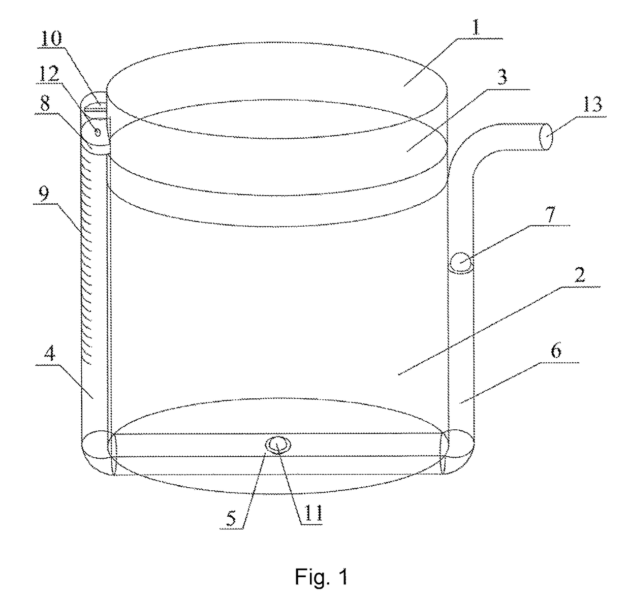
[0076]FIG. 1 shows a container according to Embodiment 1 of the present invention. A main body part 1 of the container is cylindrical and contains liquid contents 2, a piston 3 is located above the liquid contents, and the piston 3 can move vertically in the main body part 1. A pressure channel is disposed on a side wall of the main body part 1. The pressure channel is composed of a pressure transmission channel 4, a removal channel 5 and an outflow channel 6 connected in series, and is attached to the side wall and a bottom wall of the main body part.

[0077]The pressure transmission channel 4 is made of a transparent material, and has scales 9 marked. A piston 8 is disposed at an upper port of the pressure transmission channel 4, the piston 8 can move downwards along the pressure transmission channel 4, and a protrusion 10 stops the piston 8 from moving upwards. The piston 8 is provided with a screw hole 12 for connecting a pressurizing rod.

[0078]The removal channel 5 is provided wi...

embodiment 2

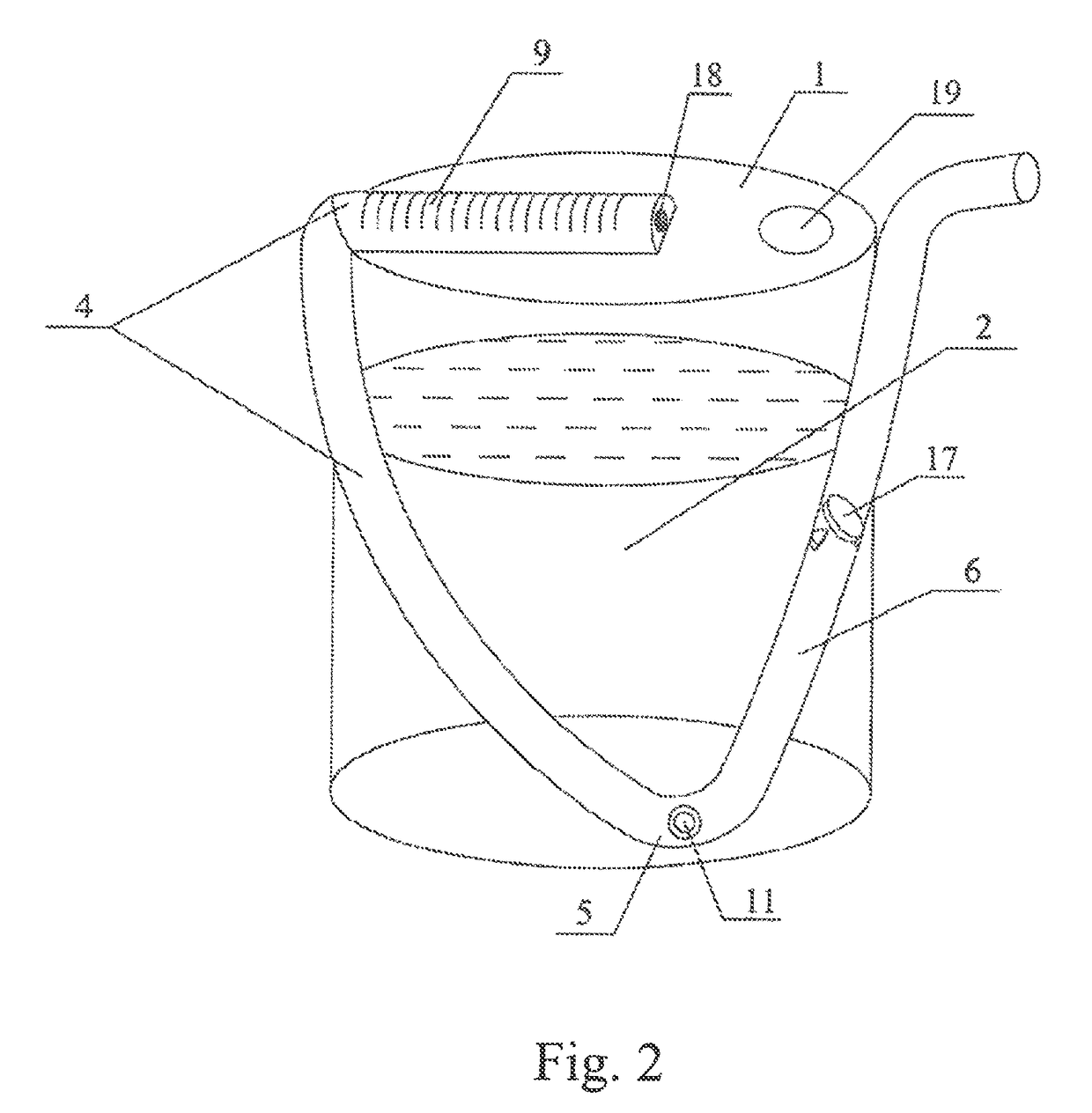
[0081]FIG. 2 shows a container according to Embodiment 2. The container includes a container main body 1, an upper part of the container main body 1 is provided with a filling opening, and after filling of the contents 2, the filling opening is sealed by using a membrane 19 merely allowing small molecular gas to pass through.

[0082]The container further includes a pressure channel attached to an upper wall and a side wall of the container main body 1 in an inclined manner, the pressure channel is composed of a pressure transmission channel 4, a removal channel 5 and an outflow channel 6 connected in series, and the pressure channel is located on the same plane. A part of the pressure transmission channel 4 is located on the upper wall of the container main body 1, and a part of the pressure transmission channel is located on the side wall of the container main body 1. A one-way valve 11 on the removal channel 5 is located at the lowest end of the pressure channel, and opens at a lowe...

embodiment 3

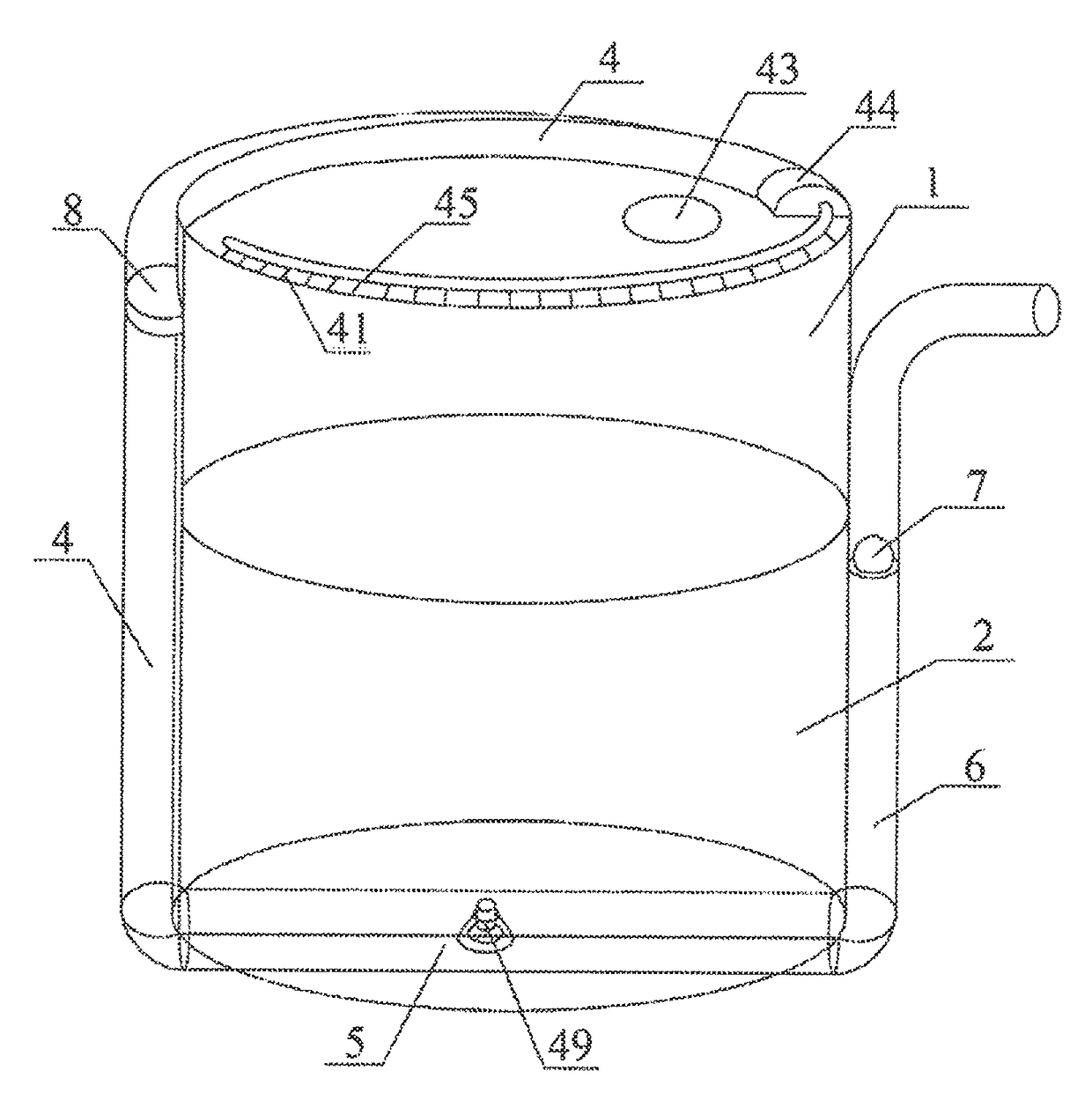
[0086]FIG. 3 and FIG. 4 show a container for containing contents according to Embodiment 3, and FIG. 4 is an enlarged diagram of a one-way valve. A main body part 1 of the container is cylindrical and contains liquid contents 2, a piston 3 is located above the liquid contents, and the piston 3 can move vertically in the main body part 1. A pressure channel is disposed on a side wall of the main body part 1. The pressure channel is composed of a pressure transmission channel 4, a removal channel 5 and an outflow channel 6 connected in series, and is attached to the side wall and a bottom wall of the main body part. The pressure transmission channel 4 is spirally attached to an outer wall of the main body part, the outflow channel 6 is attached to an inner wall of the main body part, and an opening of the outflow channel 6 is located outside the container.

[0087]The pressure transmission channel 4 is made of a transparent material, and has scales 9 marked. A piston 8 is disposed at an ...


PUM


Abstract

A container used in daily life comprises a container main body, and a pressure channel composed of a pressure transmission channel, a removal channel and an outflow channel connected in series. The pressure channel, attached to a wall of the container main body, has one end in communication with the removal channel and the other end connectable to a pressurizing component provided externally. The pressure transmission channel transmits pressure exerted on the inside of the pressure transmission channel by the pressurizing component provided externally, via a pressure transmission medium inside the channel. A wall of the removal channel is provided with a one-way valve allowing the contents to flow into the pressure channel. The one-way valve opens at the bottom on the inside of the container main body. The outflow channel is used for flowing out the contents from the container and preventing the contents flowing back.

Description

[0001]This application is a National phase filing of the International Application PCT / CN2013 / 000773, filed on Jun. 27, 2013, which claims the benefit of Chinese Patent Application No. 201210214908.3, filed on Jun. 27, 2012. All of these applications are incorporated by reference in their entirety.BACKGROUND[0002]Technical Field[0003]The present invention relates to a container used in daily life, particularly to a cheap container suitable for mass integrated production and a container from which contents in the container can be removed conveniently and rapidly.[0004]Related Art[0005]Nowadays, daily products of people are increasingly rich, for example, liquid and cream products such as hand sanitizer, laundry detergent, disinfectant, liquid shampoo, shower gel, toothpaste, soybean sauce, vinegar, cooking oil, liquid chemicals, cosmetics, and health care products. However, containers for containing the products, although having various shapes, have few novel structures, and have no ...

Claims


Application Information

Patent Timeline
Patent Type & Authority Patents(United States)
IPC IPC(8): B65D83/00B65D25/38B65D25/28B65D25/20G01F15/00G01F11/06G01F11/02G01F11/04B65D25/56B05B9/08
CPCB65D83/0005B65D25/20B65D25/28B65D25/38B65D25/56B65D83/00G01F11/025G01F11/04G01F11/06G01F15/005B05B9/0816B05B9/0883G01F13/00
Inventor CHEN, ZENGXIN
Owner BEIJING RED SEA TECH
Why Eureka
Try Eureka