Active design of exhaust sounds

a technology of active design and exhaust gas, applied in the direction of electrophonic musical instruments, machines/engines, instruments, etc., can solve the problems of reducing the efficiency of the combustion engine, destructive interference, and the sound actually leaving the exhaust gas system is not appealing to a user

Active Publication Date: 2017-08-08
PUREM GMBH
View PDF40 Cites 4 Cited by
  • Summary
  • Abstract
  • Description
  • Claims
  • Application Information

AI Technical Summary

Benefits of technology

[0011]Embodiments are directed to the provision of an active noise control system that is particularly compact and thus requires only a small space of the undercarriage of the vehicle with an internal combustion engine.
[0014]According to an embodiment, the at least one electro-acoustical transducer may be completely surrounded by the first casing. Thus, the first casing prevents the at least one electro-acoustical transducer against external influences such as moisture or mechanical impact.
[0019]According to an embodiment, the sound generator further comprises at least one flexible membrane coupled to the first casing in an air-tight manner so as to separate the at least one electro-acoustical transducer from the exhaust gas inlet and the exhaust gas outlet. By the provision of a flexible membrane corrosive exhaust gas can be prevented from reaching the at least one electro-acoustical transducer while sound waves generated by the at least one electro-acoustical transducer still can enter the first casing via the flexible membrane. The flexible membrane may be made of heat-resisting silicone or a heat-resisting foil made of Polytetrafluoroethylene, an acryloyl group, or polyethylene terephthalate, for example. Furthermore, the thermal load on the at least one electro-acoustical transducer is reduced as the at least one electro-acoustical transducer is not in direct contact with the hot exhaust gas.
[0028]According to an embodiment, at least one of the bridge walls is perforated or all bridge walls are perforated. According to a further embodiment, at least one of the conduits is perforated or all conduits are perforated. According to a further embodiment, at least one of the bridge walls is unperforated or all of the bridge walls are unperforated. According to yet another embodiment, at least one of the conduits is unperforated or all of the conduits are unperforated. Consequently, both some or all of the bridge walls and some or all of the conduits may be perforated or unperforated, or some or all of the bridge walls may be perforated and some or all of the conduits may be unperforated, or some or all of the bridge walls may be unperforated and some or all of the conduits may be perforated. It is emphasized that neither the bridge walls nor the conduits must be perforated over the whole extension thereof. For example, the conduits may only be perforated in a section, or not at all. Perforation of the bridge walls and / or conduits may facilitate the provision of a Helmholz-resonance.
[0030]According to an embodiment, the sound generator further comprises at least one second casing different from the first casing, the second casing being attached to the first casing or being housed in and supported by the first casing, wherein the second casing houses the at least one electro-acoustical transducer. The second casing may protect the at least one electro-acoustical transducer against external influences such as water or mechanical impact. Usage of the second casing may facilitate mounting of the at least one electro-acoustical transducer in the first casing or to the first casing.

Problems solved by technology

Furthermore, it is known to provide mufflers with resonating chambers harmonically tuned to cause destructive interference wherein opposite sound waves cancel each other out.
It is a disadvantage with such systems that they increase the back pressure of the exhaust gas flowing in the exhaust gas system, thus decreasing efficiency of the combustion engine.
It is a further disadvantage with such systems that, especially in the case of modern diesel vehicles, and vehicles with hybrid drive systems, the sound actually leaving the exhaust gas system is not appealing to a user.
It is a disadvantage with such active sound systems that they need to be fail-safe to meet legal provisions of noise protection.
However, the space in the undercarriage of a vehicle is very limited.

Method used


Image

  • Active design of exhaust sounds
  • Active design of exhaust sounds
  • Active design of exhaust sounds

Examples


first embodiment

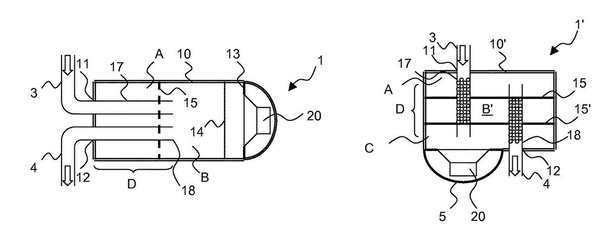
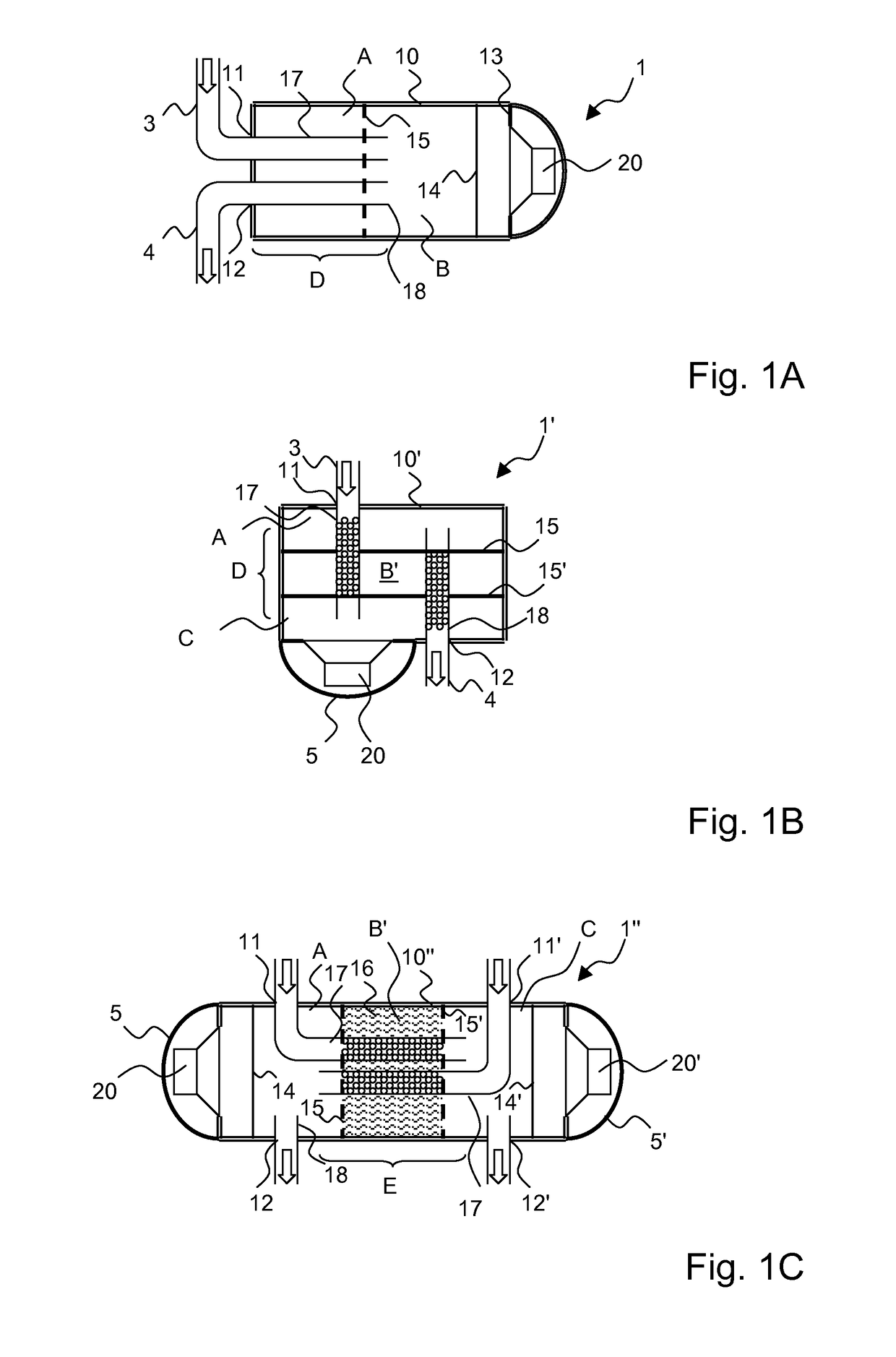
[0047]A schematic cross-sectional view of a sound generator for an active noise control system is shown in FIG. 1A.

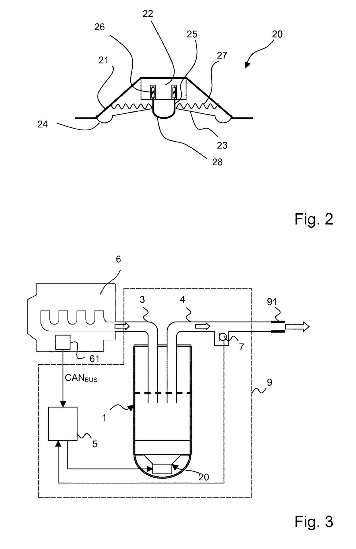
[0048]The sound generator marked overall with reference number 1 comprises a generally cylinder-shaped casing 10 made of stainless steel. An exhaust gas inlet 11 connected to a supply duct 3 and an exhaust gas outlet 12 connected to an exhaust duct 4 are provided at a basal plane of the casing 10. The supply duct 3 may become fluidly connected to a combustion engine of a vehicle and the exhaust duct 4 may become fluidly connected to a tailpipe. A perforated bridge wall 15 made of stainless steel is coupled to the casing 10 so as to define two chambers A, B within the casing 10. The chambers A, B are separated from one another by the bridge wall 15. The supply duct 3 connected to the exhaust gas inlet 11 continues within the casing 10 as an unperforated supply conduit 17, and the exhaust duct 4 connected to the exhaust gas outlet 12 continues within the casing 10 as an ...

second embodiment

[0049]In the following, a sound generator 1′ is explained by reference to FIG. 1B. FIG. 1B shows a schematic cross-sectional view of the sound generator 1′.

[0050]The sound generator marked overall with reference number 1′ comprises a (first) generally cube-shaped casing 10′ made of zinc coated tinplate. An exhaust gas inlet 11 connected to a supply duct 3 and an exhaust gas outlet 12 connected to an exhaust duct 4 are provided at opposing sides of the casing 10′. Two parallel unperforated bridge walls 15, 15′ made of zinc coated tinplate are coupled spaced-apart from one another to the casing 10′ so as to define three chambers A, B′, C within the casing 10′. The supply duct 3 connected to the exhaust gas inlet 11 continues within the casing 10′ as a supply conduit 17, and the exhaust duct 4 connected to the exhaust gas outlet 12 continues within the casing 10′ as a exhaust conduit 18. Within the casing 10′, the supply conduit 17 and the exhaust conduit 18 are arranged in parallel in...

third embodiment

[0051]In the following, a sound generator 1″ is explained by reference to FIG. 1C. FIG. 1C shows a schematic cross-sectional view of the sound generator 1″.

[0052]The sound generator marked overall with reference number 1″ comprises a generally cylinder-shaped casing 10″ made of stainless steel. Two exhaust gas inlets 11, 11′ each connected to an supply duct and two exhaust gas outlets 12, 12′ each connected to an exhaust duct are provided at opposing sides of the casing 10″. Two parallel perforated bridge walls 15, 15′ made of stainless steel are coupled spaced-apart from one another to the casing 10″ so as to define three chambers A, B′, C within the casing 10″. The supply ducts connected to the exhaust gas inlets 11, 11′ each continue within the casing 10″ as a supply conduits 17, 17′ and the exhaust ducts connected to the exhaust gas outlets 12, 12′ each continue within the casing 10″ as a exhaust conduits 18, 18′. The supply conduits 17, 17′ are bent such that within the casing ...


PUM


Abstract

A sound generator (1) includes a casing (10) with at least one exhaust gas inlet (11) and at least one exhaust gas outlet (12) that is different from the at least one exhaust gas inlet (11) and at least one electro-acoustical transducer (20). The electro-acoustical transducer (20) is configured to produce sound in dependence on an electrical control signal. The electro-acoustical transducer (20) is located within the casing or directly attached to the casing. An active noise control system (9) includes the sound generator (1). A vehicle (8) with an internal combustion engine (6) includes the active noise control system (9).

Description

CROSS REFERENCE TO RELATED APPLICATIONS[0001]This application claims the benefit of priority under 35 U.S.C. §119 of European Patent Application EP 14 157 687.6 filed Mar. 4, 2014, the entire contents of which are incorporated herein by reference.FIELD OF THE INVENTION[0002]The invention concerns the active design of exhaust sounds for vehicles that are operated with internal combustion engines. The internal combustion engine may be part of a hybrid drive unit. The invention relates in particular to the influencing of the overall acoustic pattern of exhaust sounds.BACKGROUND OF THE INVENTION[0003]The operation of internal combustion engines, regardless of the particular internal combustion engine design, such as reciprocating engines, piston-less rotary engines or free-piston engines, occurs in repeated strokes in each of which certain processes are carried out, such as intake and compression of a fuel and air mixture, combustion, and discharging of the combusted fuel air mixture, o...

Claims


Application Information

Patent Timeline
Patent Type & Authority Patents(United States)
IPC IPC(8): H03G3/00F01N1/02F01N1/04F01N1/06G10K11/175G10H5/10H04R1/00
CPCG10H5/10F01N1/023F01N1/04F01N1/065G10K11/175H04R1/00F01N2310/02F01N2470/02F01N2470/14F01N2470/16F01N2470/18F01N2470/22F01N2490/08G10K2210/12822G10K2210/32272H04R2499/13
Inventor KECK, MATHIASROMZEK, MARTIN
Owner PUREM GMBH
Why Eureka
Try Eureka