Self-propelling work machine and method for braking such a work machine

a work machine and self-propelling technology, applied in mechanical machines/dredgers, battery/fuel cell control arrangements, vehicle sub-unit features, etc., can solve the problems of inability to provide, mechanical brakes can only be connected substantially, and the braking power of electric motors is not easy to achieve. , to achieve the effect of reducing operating costs, improving efficiency and facilitating maintenan

Active Publication Date: 2017-08-29
LIEBHERR COMPONENTS BIBERACH GMBH
View PDF21 Cites 5 Cited by
  • Summary
  • Abstract
  • Description
  • Claims
  • Application Information

AI Technical Summary

Benefits of technology

[0003]With self-propelling work machines such as dump trucks, trucks or other self-propelling off-road vehicles for construction sites, mines and the like, electric drives having at least one electric motor have been used in recent times to utilize the typical advantages of such electric drives with respect to hydrostatic drives such as their better efficiency and an easier maintenance.

Problems solved by technology

The distribution of the electrical motor braking power, however, requires a relatively complicated control system while taking account of the electrical energy usable at the auxiliary units.
The feedback apparatus can so-to-say be configured in one strand and cannot provide any branches or junctions which would transfer different portions of the fed back motor braking power to different drive elements.
Wit

Method used


Image

  • Self-propelling work machine and method for braking such a work machine
  • Self-propelling work machine and method for braking such a work machine
  • Self-propelling work machine and method for braking such a work machine

Examples


Embodiment Construction

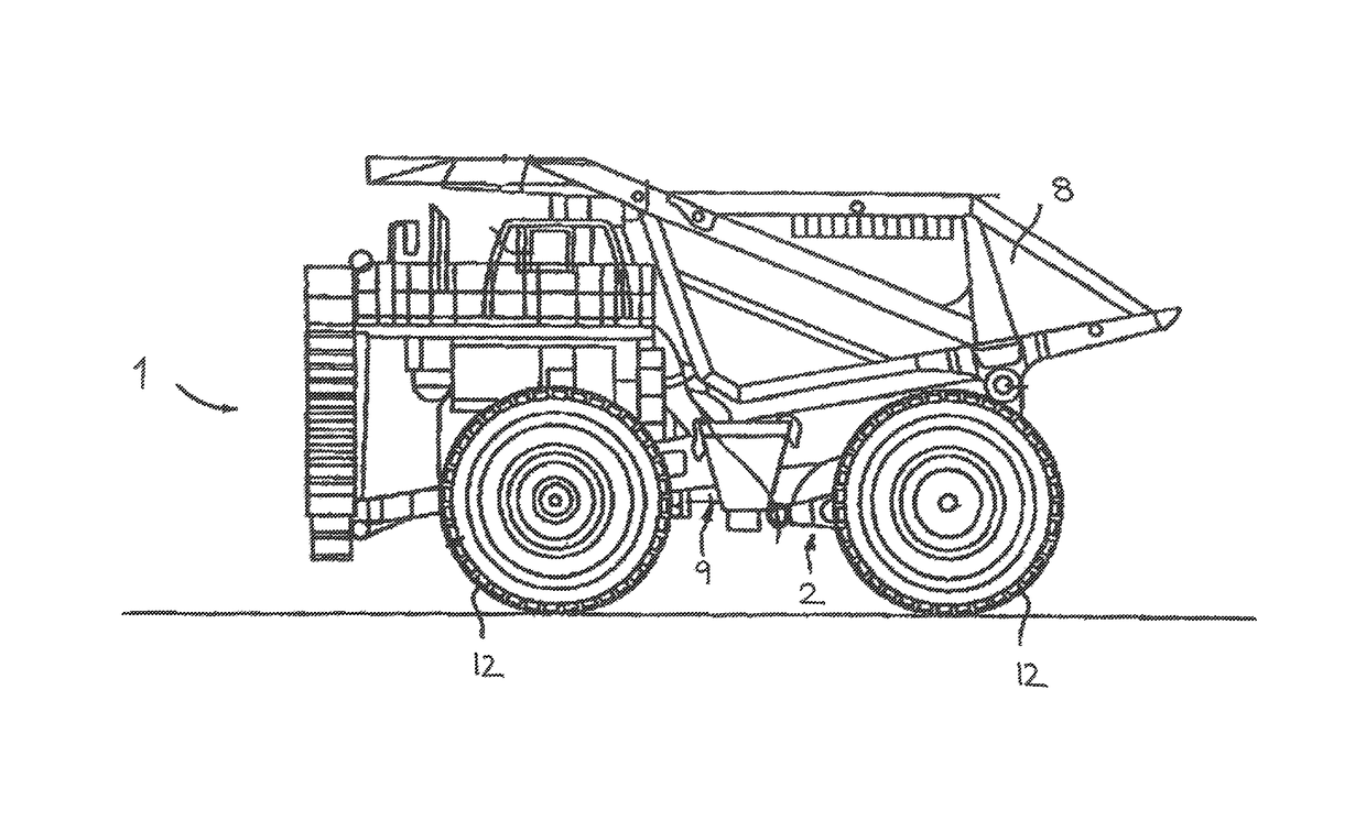
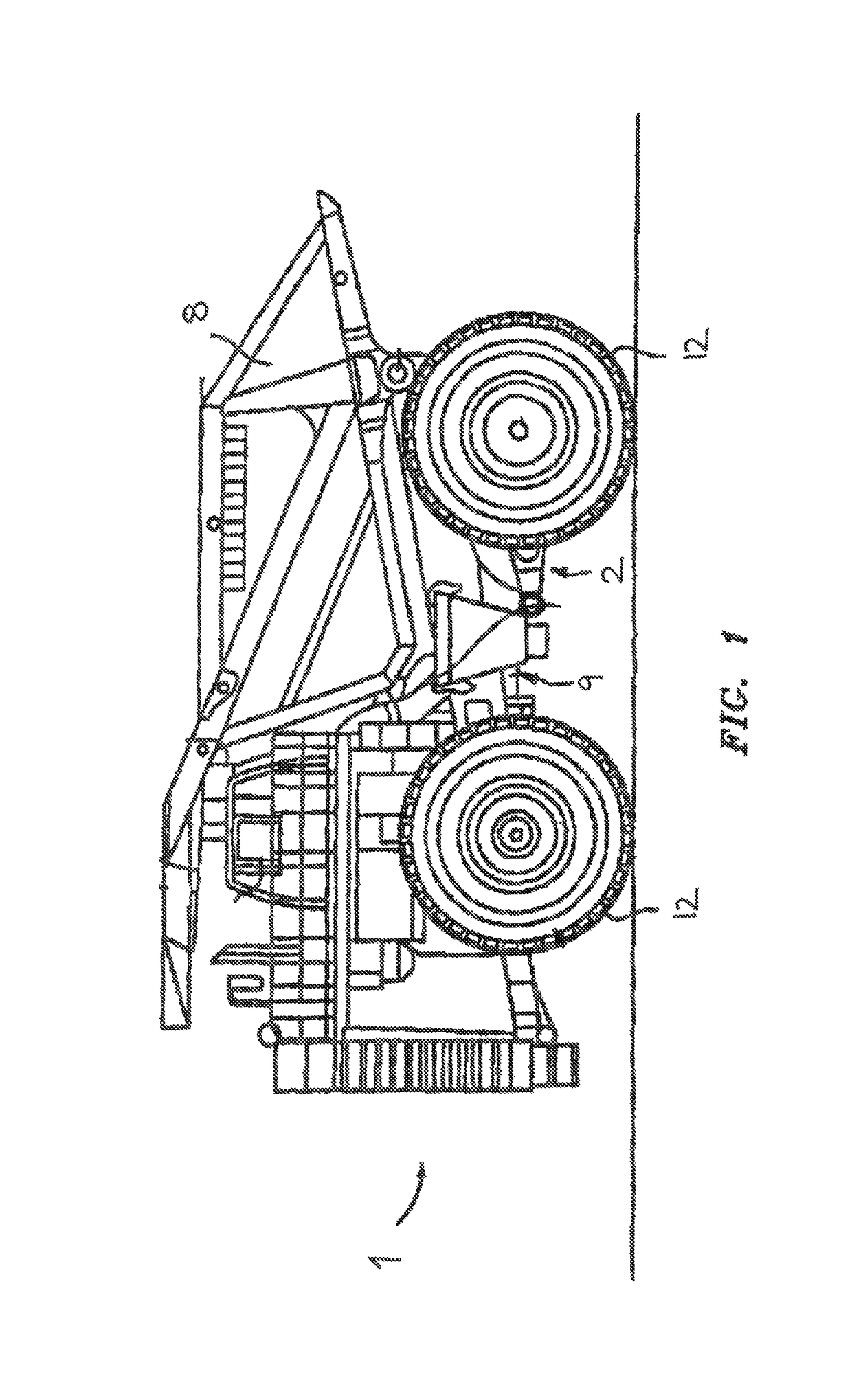
[0024]As FIG. 1 shows, the self-propelling work machine 1 can be configured, for example, as an off-road truck, in particular in the form of a dump truck, and can comprise as an undercarriage 2 a plurality of wheels 12 which are distributed over a plurality of axles and which support the chassis or the frame of the work machine 1. It is, however, understood that the work machine can generally also be configured in another form, for example in the form of another construction machine or mining machine having a wheel undercarriage or chain undercarriage.

[0025]The drive systems of the work machine 1 comprise at least one electric drive 3 having at least one electric motor 4 which can serve as a traction drive and which can drive the wheels 12. In this respect, one electric motor 4 can simultaneously drive a plurality of wheels 12, for example the wheels 12 of an axle, optionally via a power-split transmission or a differential. Alternatively, a single wheel drive can also be provided i...


PUM


Abstract

The application describes a self-propelling work machine, in the form of a truck, having an electric drive comprising at least one electric motor, a generator drivable by an internal combustion engine for the power supply of the electric drive, and a braking apparatus for braking the work machine, wherein the braking apparatus provides a regenerative braking by the electric drive and a feedback apparatus for feeding back electrical motor braking power of the electric motor to the generator to apply the motor braking power on the internal combustion engine. The application further describes a method for braking the work machine. A braking control apparatus is provided for an automatic connection of a mechanical brake in dependence on the motor braking power fed back to the internal combustion engine and/or in dependence on the operating state of the internal combustion engine acted on by the fed back motor braking power.

Description

CROSS REFERENCE TO RELATED APPLICATIONS[0001]The present application is a U.S. National Phase of International Patent Application Serial No. PCT / EP2014 / 002437, entitled “Self-Propelled Working Machine and Method for Braking a Working Machine of This Type,” filed on Sep. 9, 2014, which claims priority to German Patent Application No. 10 2013 021 608.7, filed on Dec. 19, 2013, and to German Patent Application No. 10 2013 016 915.1, filed Oct. 11, 2013, and to German Patent Application No. 10 2013 016 126.6, filed Sep. 27, 2013, the entire contents of each of which are hereby incorporated by reference in their entirety for all purposes.TECHNICAL FIELD[0002]The present invention relates to a self-propelling work machine, preferably in the form of a dump truck or of a truck, having an electric drive comprising at least one electric motor, a generator drivable by an internal combustion engine for the power supply of the electric drive and a braking apparatus for braking the work machine, ...

Claims


Application Information

Patent Timeline
IPC IPC(8): B60L7/10B60W10/184B60W10/08B60W10/06B60K6/46B60L11/18B60W10/196B60W10/30B60W20/00B60W30/18E02F9/20E02F3/76B60W20/14B60L7/18B60L11/02B60K6/22B60K25/00B60W10/18B60W10/24B60K6/28B60L50/10
CPCB60L11/1851B60K6/22B60K6/46B60K25/00B60L7/10B60L7/18B60L11/02B60L11/1809B60W10/06B60W10/08B60W10/18B60W10/184B60W10/196B60W10/24B60W10/30B60W20/00B60W20/14B60W30/18127B60W30/18136E02F3/7609E02F9/2075E02F9/2083B60K6/28B60L2200/40B60W2300/125B60W2300/17B60W2710/0627B60W2710/0644B60Y2200/411B60Y2200/92B60Y2300/18125B60Y2300/43B60Y2300/60B60Y2300/91B60Y2400/604B60Y2400/61B60Y2400/81B60Y2400/87Y02T10/6217Y02T10/6286Y10S903/93Y10S903/947B60L50/10B60L53/00B60L58/10B60L53/50Y02T10/70Y02T10/7072Y02T90/14Y02T90/12Y02T10/62
Inventor HOFFMANN, SEBASTIEN NICOLASRICHTHAMMER, BURKHARD EMANUELSOMMER, BERNDDUELLI, STEFANMERKLE, MARKUSRESCH, JUERGEN
Owner LIEBHERR COMPONENTS BIBERACH GMBH
Why Eureka
Try Eureka