Removable rack mountable power cell

a power cell and rack mount technology, applied in the direction of electrical apparatus construction details, casings/cabinets/drawers, casings/cabinets/drawers, etc., can solve the problem that both components are required to be replaced at an added cost, and achieve the effect of increasing circuit capacity, reducing downtime, and increasing safety for mine personnel

Active Publication Date: 2017-09-05
SMC ELECTRICAL PROD
View PDF11 Cites 8 Cited by
  • Summary
  • Abstract
  • Description
  • Claims
  • Application Information

AI Technical Summary

Benefits of technology

[0008]A primary objective of the present invention is to provide methods, systems and devices for a modular quick change out power cell to reduce downtime, increase circuit capacity all in a very compact design with increased safety to mine personnel.

Problems solved by technology

As a result, when one of the power or the control components fails, both of the components are required to be replaced at an added expense.

Method used


Image

  • Removable rack mountable power cell
  • Removable rack mountable power cell
  • Removable rack mountable power cell

Examples


Embodiment Construction

[0041]Before explaining the disclosed embodiments of the present invention in detail it is to be understood that the invention is not limited in its application to the details of the particular arrangements shown since the invention is capable of other embodiments. Also, the terminology used herein is for the purpose of description and not of limitation.

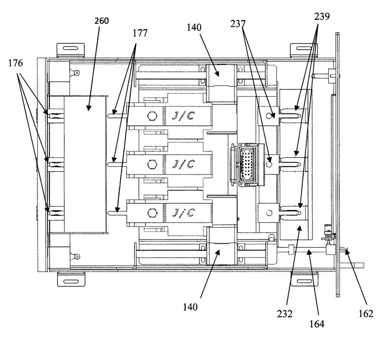
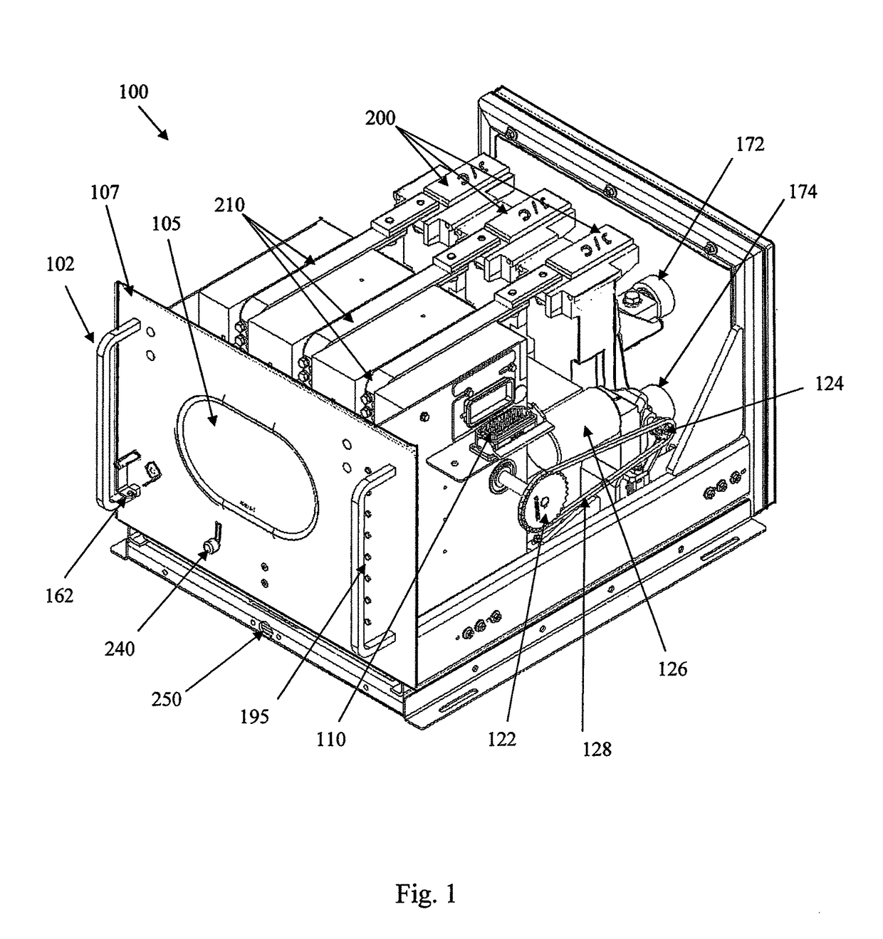
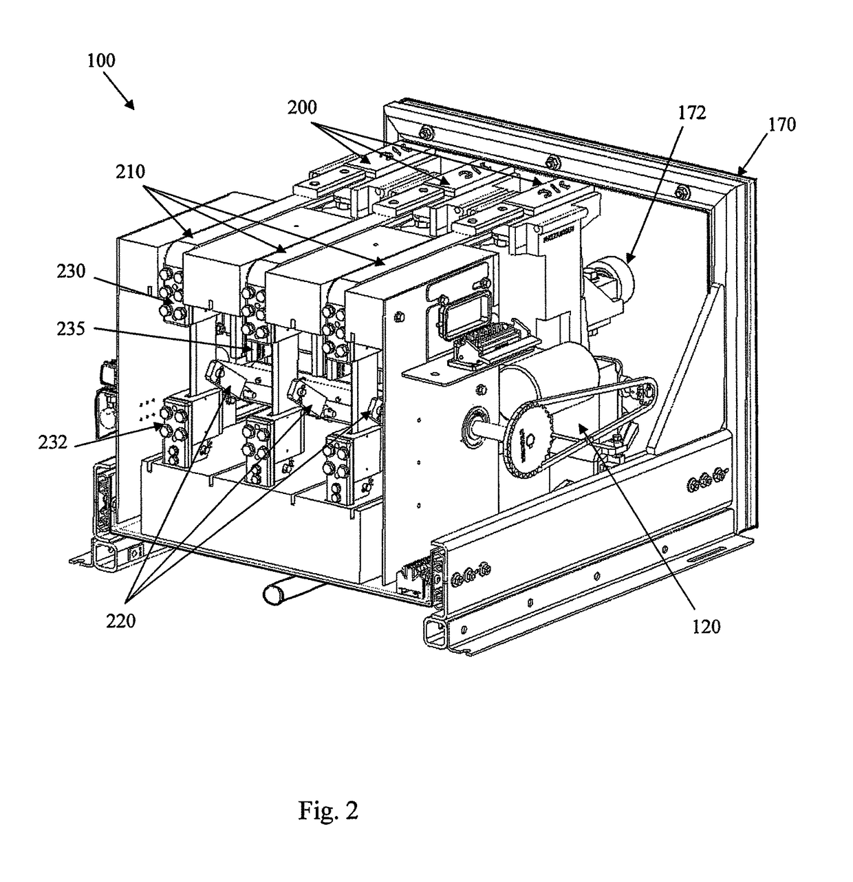
[0042]The following is a list of reference numerals used in the description and the drawings to identify components:[0043]100 removable motor power cell[0044]102 handle[0045]105 window[0046]107 front panel[0047]110 controller signal connector[0048]120 motor assembly[0049]122 large sprocket[0050]124 small sprocket[0051]126 motor[0052]128 sprocket chain[0053]130 shaft between large sprocket and rack[0054]135 actuator[0055]140 rack and pinion assembly[0056]142 rack[0057]144 pinion[0058]146 rack pinion moving assembly[0059]148 switch bracket[0060]152 lock out micro switch[0061]154 upper limit switch (open and grounded)[0062]156 lower lim...


PUM


Abstract

A removable electrical power cell including an incoming electrical source connector with a circuit interrupting device and an electrically isolated outgoing electrical load connector, an electro-mechanical switching assembly connected to a movable disconnect switch to move the disconnect switch between an open and grounded position and a closed and energized position and a controller to provide an input signal for controlling the operation of the electro-mechanical switching assembly to control an operation of the removable electrical power cell. The electro-mechanical switching assembly includes a rack and pinion switching assembly and a lockout limit switch to control operation of the automatic power switching assembly. The electro-mechanical switching assembly including a motor driven switching assembly to automatically open and close the high voltage power isolation switch based on an incoming signal. The motorized removal power cell including a lock out assembly to prevent removing the power cell when closed and energized.

Description

[0001]This applicant claims the benefit of priority to U.S. Provisional Application No. 61 / 703,459 filed on Sep. 20, 2012.FIELD OF THE INVENTION[0002]This invention relates to rack mountable electrical equipment and, in particular, to methods, systems and devices for a removal motor power cell for bolt in rack mounted electrical equipment using motorized mechanical switching for connecting and disconnecting high voltage electrical power via an automatic or remotely operated power switching assembly coupled with the motorized mechanical switching.BACKGROUND[0003]A complete 5 KV motor circuit includes power components relating the 5K volt rack mounted power cell and low voltage control protective relaying which include a ground fault relay, ground wire monitor, short circuit and overload relays. The prior art 5 KV pull out cells use a single draw out assembly consisting of both power and control components. As a result, when one of the power or the control components fails, both of th...

Claims


Application Information

Patent Timeline
Patent Type & Authority Patents(United States)
IPC IPC(8): H02B11/02H02B11/28H02B11/00H02B11/10H05K5/02
CPCH05K5/0247H02B11/28H02B11/00H02B11/10H02B11/02H02B1/36H05K7/14325H05K7/1432
Inventor HANDSHOE, SAM
Owner SMC ELECTRICAL PROD
Why Eureka
Try Eureka