Catheters and methods for intracardiac electrical mapping

a catheter and electrical mapping technology, applied in catheters, applications, therapy, etc., can solve problems such as the termination of electrical conduction

Active Publication Date: 2017-10-31
MEDTRONIC ABLATION FRONTIERS
View PDF19 Cites 7 Cited by
  • Summary
  • Abstract
  • Description
  • Claims
  • Application Information

AI Technical Summary

Benefits of technology

[0007]The system and method of the present application provides a non-ambiguous representation of the electrical activity of the myocardium at each particular site within or on the heart, improved means for searching for and testing potential ablation sites including both ectopic foci and rotors, and both mapping and treatment functionality. The non-ambiguous representation of local myocardial depolarization, repolarization timing, and action potential duration is enabled through the use of electrodes that are able to record local monophasic action potentials (MAPs).

Problems solved by technology

Furthermore, treating the cardiac cells at the source or pathway of electrical conduction of interest at a lethal temperature may terminate the electrical conduction of interest.

Method used


Image

  • Catheters and methods for intracardiac electrical mapping
  • Catheters and methods for intracardiac electrical mapping
  • Catheters and methods for intracardiac electrical mapping

Examples


first embodiment

[0035]Now referring to FIG. 7, a distal portion 20 of a medical device 12 with mapping and ablation functionality is shown. The distal portion 20 may have a coil or concentric spiral configuration 54 with a plurality of turns. The coil or concentric spiral 54 may lie in a plane that is substantially orthogonal to the longitudinal axis 28 of the device 12. Each turn includes an anterior face 56, on which is positioned one or more mapping elements 24 and / or one or more treatment elements 26. If the spiral 54 is the treatment element 26, then the face 56 of the spiral 54 may only contain mapping elements 24. To enhance surface area and tissue contact, the one or more mapping 24 and / or treatment elements 26 may have a curved or semi-circular profile that extends from the anterior face 56 of each turn of the spiral 54 (for example, as shown in FIG. 11). As a non-limiting example, as shown in FIG. 7, the spiral 54 is the treatment element 26 on which a plurality of mapping elements 24 are...

second embodiment

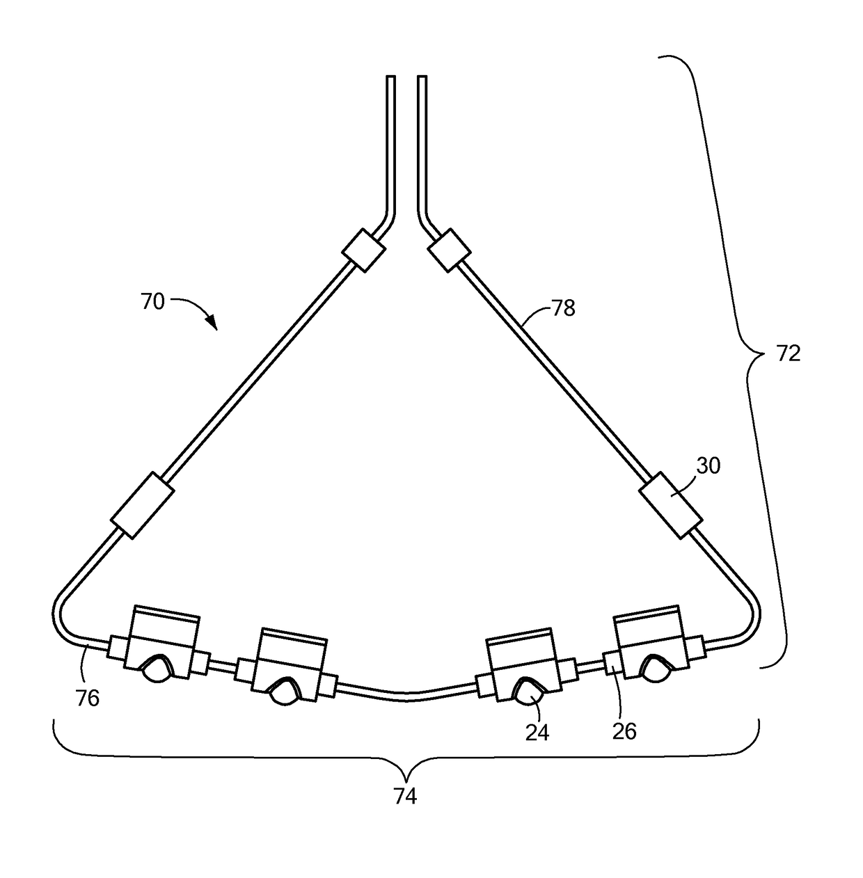
[0036]Now referring to FIG. 8, a distal portion 20 of a medical device 12 with mapping 24 and ablation functionality is shown. The distal portion 20 may include a crossed-arm array 60 that includes a plurality of arms 62, each of which bearing one or more mapping 24 and / or treatment elements 26 at an anterior face 64 of the array 60. Each arm 62 may include a first portion 66 at the anterior face 64 of the array 60 on which the one or more mapping 24 and / or treatment elements 26 are borne, and a second portion 68 that is coupled to the device 12. Each electrode may serve a mapping and / or ablation function, and it is conceived that mapping elements 24 may protrude from underlying ablative structures (as shown and described in FIGS. 11 and 13). The point at which the first 66 and second 68 portion of each arm 62 meet may form an acute angle. The second portion 68 of each arm 62 may be affixed to a shaft 58 that is slidably movable within the elongate body 18 of the device 12, or affix...

third embodiment

[0037]Now referring to FIG. 9, a distal portion 20 of a medical device 12 with mapping and ablation functionality is shown. The device 12 may be a focal catheter or similar device, without a distal array or configuration and the one or more mapping 24 and / or treatment elements 26 (referred to in FIG. 9 as “24 / 26”) being borne along the distal portion 20 of the elongate body 18. Alternatively, the distal portion 20 of the device 12 may be composed of a material different than that of the elongate body 18, may have a different diameter or rigidity, or the like. To enhance surface area and tissue contact, the one or more mapping 24 and / or treatment elements 26 may have a curved or semi-circular profile that extends from the distal portion 20 (for example, as shown in FIG. 10). Alternatively, the one or more mapping 24 and / or treatment elements 26 may be set within and flush with the distal portion 20 (for example, as shown in FIG. 11). Additionally, the distal portion 20 may be compose...


PUM


Abstract

A method and system capable of identifying ectopic foci, rotors, or conduction pathways involved in reentrant arrhythmias within cardiac tissue, and then treating identified ectopic foci, rotors, and / or pathways with either lethal or sub-lethal temperatures. The system includes a medical device having one or more mapping elements and one or more treatment elements, and a computer programmable to identify ectopic foci and rotors based at least in part on signals received from the one or more mapping elements at one or more locations.

Description

CROSS-REFERENCE TO RELATED APPLICATION[0001]This application is related to and claims priority to U.S. Provisional Patent Application Ser. No. 61 / 684,380, filed Aug. 17, 2012, entitled CATHETERS FOR ROTOR MAPPING, the entirety of which is incorporated herein by reference.STATEMENT REGARDING FEDERALLY SPONSORED RESEARCH OR DEVELOPMENT[0002]n / aFIELD OF THE INVENTION[0003]The present invention relates to a method and system for cardiac mapping and ablation.BACKGROUND OF THE INVENTION[0004]A cardiac arrhythmia is a condition in which the heart's normal rhythm is disrupted. There are many types of cardiac arrhythmias, including supraventricular arrhythmias that begin above the ventricles (such as premature atrial contractions (PACs), atrial flutter, accessory pathway tachycardias, atrial fibrillation, and AV nodal reentrant tachycardia (AVNRT)), ventricular arrhythmias that begin in the lower chambers of the heart (such as premature ventricular contractions (PVCs), ventricular tachycardi...

Claims


Application Information

Patent Timeline
Patent Type & Authority Patents(United States)
IPC IPC(8): A61B5/04A61B18/18A61B5/042A61B18/14A61B5/0408A61B5/00A61N1/32A61B18/24A61B18/02A61B18/00
CPCA61B18/1492A61B5/04085A61B5/6852A61B5/042A61N1/327A61B5/6855A61B18/24A61B2018/00267A61B2018/00351A61B2018/00577A61B2018/00613A61B2018/00839A61B2018/0212A61B2018/1435A61B2505/05A61B5/282A61B5/283
Inventor LASKE, TIMOTHY G.KNIGHT, JOSEPH ALLENGROVES, REGINA E.
Owner MEDTRONIC ABLATION FRONTIERS
Why Eureka
Try Eureka