Physiological monitoring system featuring floormat and wired handheld sensor

a monitoring system and sensor technology, applied in the field of sensors, can solve the problems of nullifying the value of such measurements, affecting treatment, and measurement errors, and achieve the effects of convenient measurement of a collection, simple form factor, and convenient us

Inactive Publication Date: 2017-07-06
TOSENSE
View PDF14 Cites 6 Cited by
  • Summary
  • Abstract
  • Description
  • Claims
  • Application Information

AI Technical Summary

Benefits of technology

[0025]In view of the foregoing, it would be beneficial to provide a monitoring system that is suitable for home use. Particularly valuable would be a single system, free of external components, that is wireless and conveniently measures a collection of vital signs and hemodynamic parameters. Ideally, such a system would feature a single device and only reusable (i.e. no disposable) sensors. The device should be easy to use and feature a simple form factor that integrates into the user's day-to-day activities. The monitoring system according to the invention, which facilitates monitoring conditions such as HF, CHF, ESRD, cardiac arrhythmias, and other diseases, is designed to achieve this very goal.

Problems solved by technology

TFC deviation in the day-to-day placement of the electrodes can result in measurement errors.
This, in turn, can lead to misinformation (particularly when trends of the measured parameters are to be extracted), thereby nullifying the value of such measurements and thus negatively impacting treatment.
Unfortunately, during a measurement, the lead wires can pull on the electrodes if the device is moved relative to the user's body, or if the user ambulates and snags the lead wires on surrounding objects.
Such pulling can be uncomfortable or even painful, particularly where the electrodes are attached to hirsute parts of the body, and this can inhibit user compliance with long-term monitoring.
Moreover, these actions can degrade or even completely eliminate adhesion of the electrodes to the user's skin, and in some cases completely destroy the electrodes' ability to sense the physiological signals at various electrode locations.
Chronic elevation of LVEDP causes transudation of fluid from the pulmonary veins into the lungs, resulting in shortness of breath (dyspnea), rapid breathing (tachypnea), and fatigue with exertion due to the mismatch of oxygen delivery and oxygen demand throughout the body.
As CO is compromised, the kidneys respond with decreased filtration capability, thus driving retention of sodium and water and leading to an increase in intravascular volume.
However, an extremely delicate balance between these two biological treatment modalities needs to be maintained, since an increase in blood pressure (which relates to afterload) or fluid retention (which relates to preload), or a significant change in heart rate due to a tachyarrhythmia, can lead to decompensated HF.
Unfortunately, this condition is often unresponsive to oral medications.
However, by itself, this parameter is typically not sensitive enough to detect the early onset of CHF—a particularly important stage when the condition may be ameliorated simply and effectively by a change in medication or diet.
These organs then respond with a reduction in their filtering capacity, thus causing the user to retain sodium and water and leading to an increase in intravascular volume.
This, in turn, leads to congestion, which is manifested to some extent by a build-up of fluids in the user's thoracic cavity (e.g. TFC).
Such cyclical pathology and treatment is physically taxing on the user, and economically taxing on society.
CHF is also the leading cause of mortality for users with ESRD, and this demographic costs Medicare nearly $90,000 / user annually.
Poor compliance (e.g. less-than-satisfactory consistency) with the use of any medical device may be particularly likely in an environment such as the user's home or a nursing home, where direct supervision may be less than optimal.

Method used


Image

  • Physiological monitoring system featuring floormat and wired handheld sensor
  • Physiological monitoring system featuring floormat and wired handheld sensor
  • Physiological monitoring system featuring floormat and wired handheld sensor

Examples


Embodiment Construction

1. System Overview

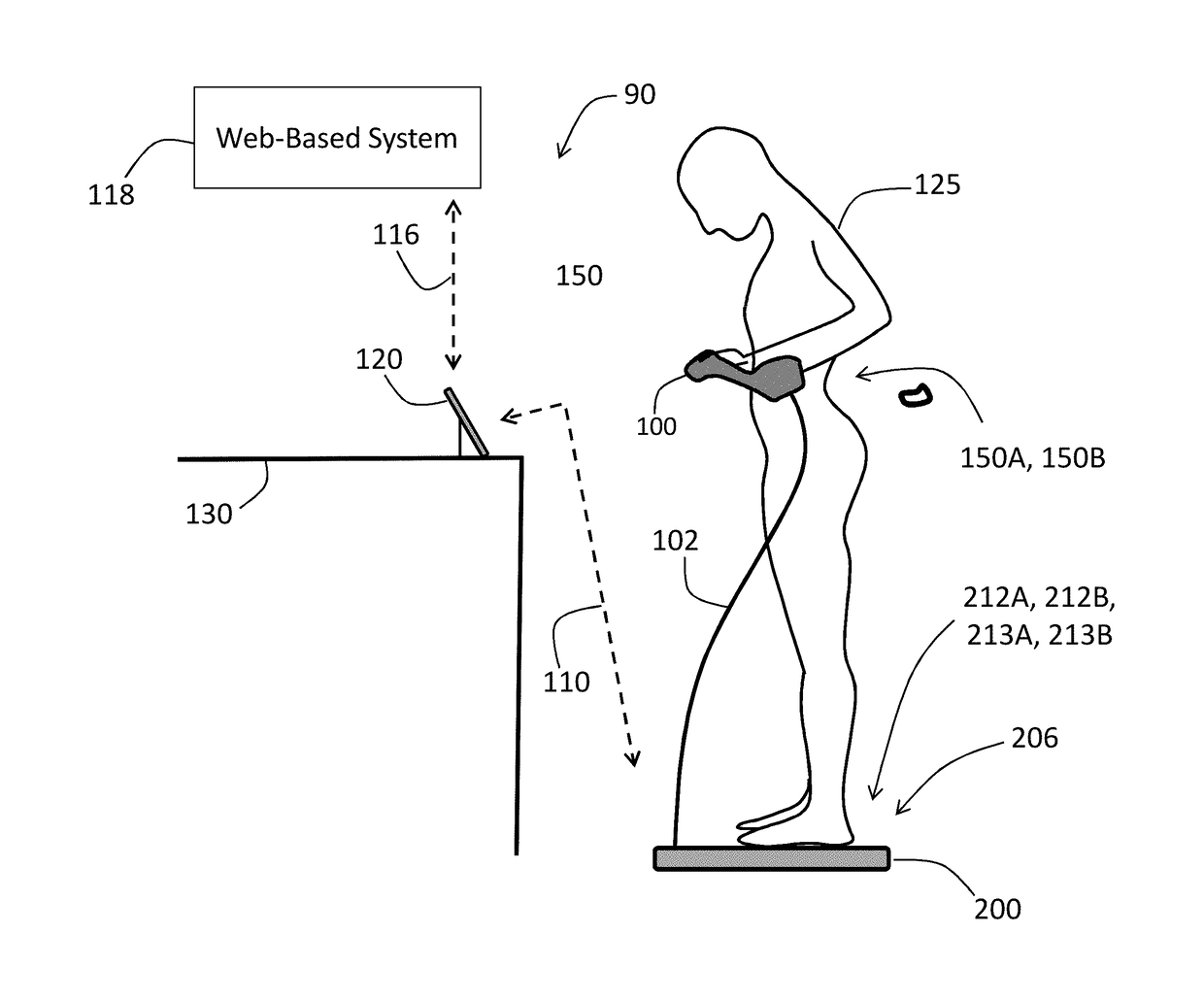
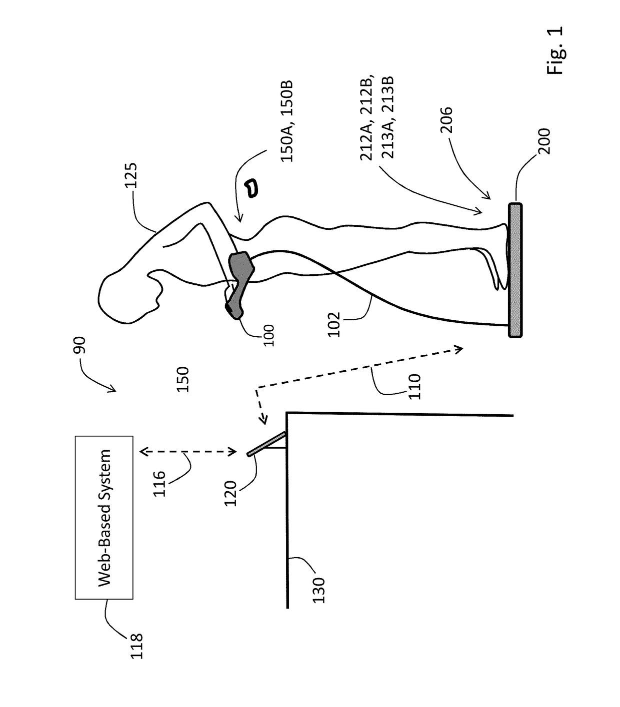
[0076]FIG. 1 shows a system 90 featuring a Floormat 200 and Handheld Sensor 100, electrically connected to each other by a conductor-bearing cable 102, that work in concert to measure a user 125 according to the invention. Both the Floormat 200 and Handheld Sensor 100 feature a collection of physiological sensors that connect to the user 125, as described in detail below, to measure time-dependent physiological waveforms, and from these physiological parameters. A wireless device (e.g. a Bluetooth® radio) within the Floormat 200 transmits both the waveforms and parameters to an external mobile device 120. The goal of the system 90 is to quickly and non-invasively measure all five vital signs (HR, RR, SpO2, BP, and TEMP), hemodynamic parameters (SV, CO, TFC, Fluids), and biometric parameters (weight, body composition) with a system 90 that is easy-to-use, low-cost, inconspicuous, and seamlessly connects to the cloud. A rationale for the system 90 is that most diseas...


PUM


Abstract

A physiological monitoring system features a Floormat and Handheld Sensor connected by a cable. A user stands on the Floormat and grips the Handheld Sensor. These components measure time-dependent physiological waveforms from a user over a conduction pathway extending from the user's hand or wrist to their feet. The Handheld Sensor and Floormat use a combination of electrodes that inject current into the user's body and collect bioelectric signals that, with processing, yield ECG, impedance, and bioreactance waveforms. Simultaneously, the Handheld Sensor measures photoplethysmogram waveforms with red and infrared radiation and pressure waveforms from the user's fingers and wrist, while the Floormat measures signals from load cells to determine ‘force’ waveforms to determine the user's weight, and ballistocardiogram waveforms to determine parameters related to cardiac contractility. Processing these waveforms with algorithms running on a microprocessor yield the vital sign, hemodynamic, and biometric parameters.

Description

BACKGROUND AND FIELD OF THE INVENTION[0001]1. Field of the Invention[0002]The invention relates to sensors that measure physiological signals from a patient (e.g. a user), and the use of such sensors.[0003]2. General Background[0004]Physiological sensors, such as vital sign monitors, typically measure signals from a user to determine time-varying waveforms, e.g. thoracic bio-impedance (TBI), bio-reactance (BR), and electrocardiogram (ECG) waveforms, with electrodes that attach to the user's skin. These waveforms can be processed / analyzed to extract other medically relevant parameters such as heart rate (HR) and heart rate variability (HRV), respiration rate (RR), stroke volume (SV), cardiac output (CO), and information relating to thoracic fluid content, e.g. thoracic fluid index (TFC) and general body fluids (Fluids). Certain physiological conditions can be identified from these parameters using one-time measurements; other conditions require observation of time-dependent trends in...

Claims


Application Information

Patent Timeline
Patent Type & Authority Applications(United States)
IPC IPC(8): A61B5/022A61B5/0452A61B5/11A61B5/00
CPCA61B5/02233A61B5/6892A61B5/0452A61B5/02416A61B5/6824A61B5/1102A61B5/742A61B5/7271A61B5/02055A61B5/0535A61B5/349
Inventor BANET, MATTHEWDHILLON, MARSHAL SINGHPEDE, SUSAN MEEKSHAYWARD, LAUREN NICOLE MILLERDEPTALA, ARTHURCOCHRAN, JONAS DEAN
Owner TOSENSE
Why Eureka
Try Eureka