[0008]An
advantage of the present invention is provision of an ultrasonic diagnostic apparatus which can quantitatively evaluate the conduction of the electric signal in the heart.
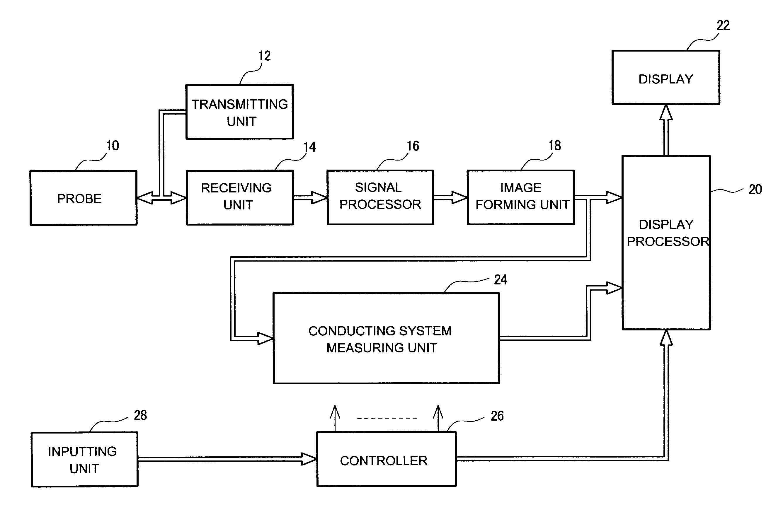
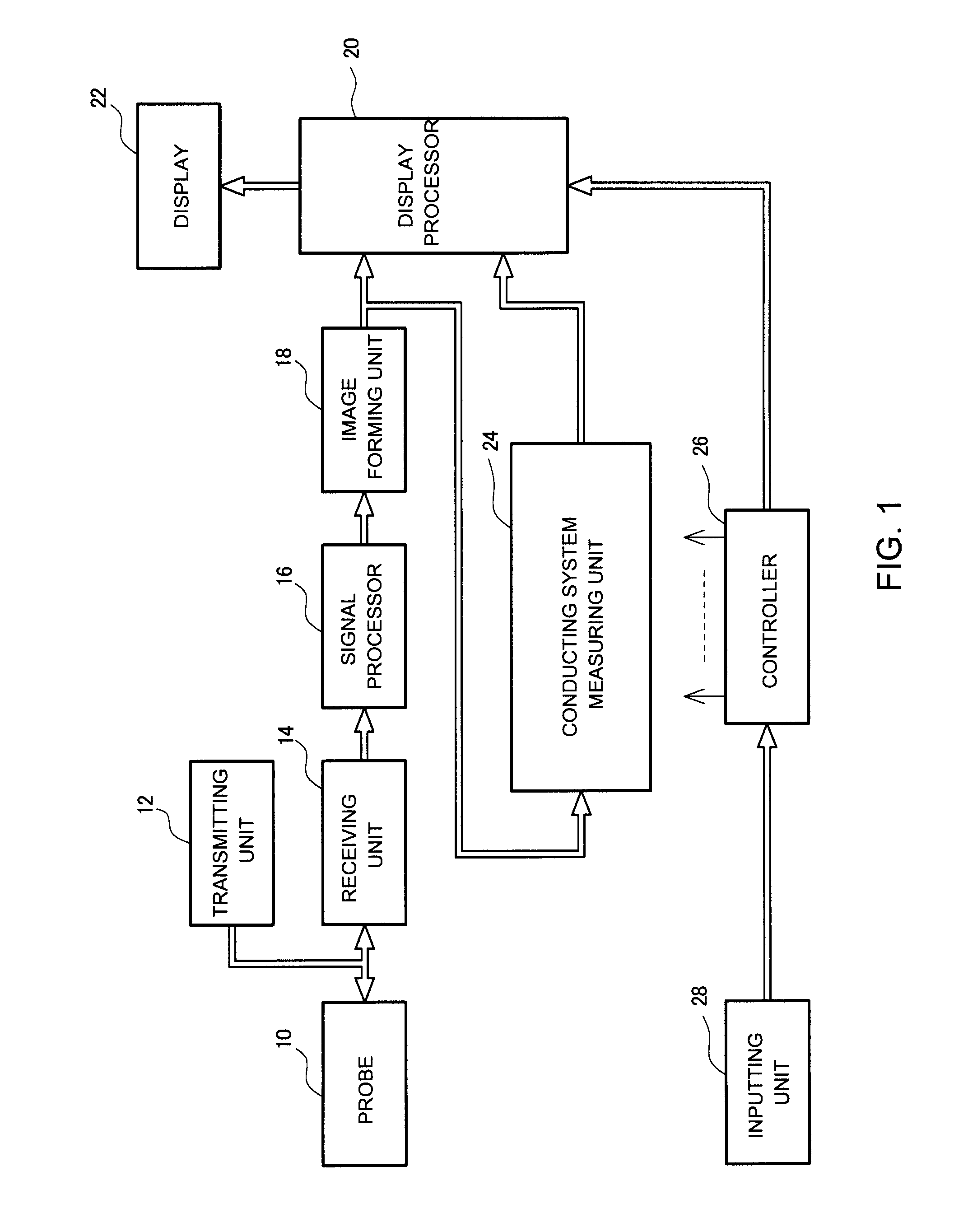
[0009]According to one aspect of the present invention, there is provided an ultrasonic diagnostic apparatus comprising a setting unit which sets, on an ultrasonic image of a heart, a plurality of observation points on conduction pathways of the heart for an electric signal which causes contraction of a cardiac
muscle; a tracking unit which tracks each of the observation points to determine a temporal displacement of each of the observation points; a waveform
generating unit which generates a plurality of displacement waveforms representing the temporal displacements for the plurality of observation points; and an analyzing unit which analyzes the plurality of displacement waveforms on a common time axis to calculate a time difference of motion for the plurality of observation points.
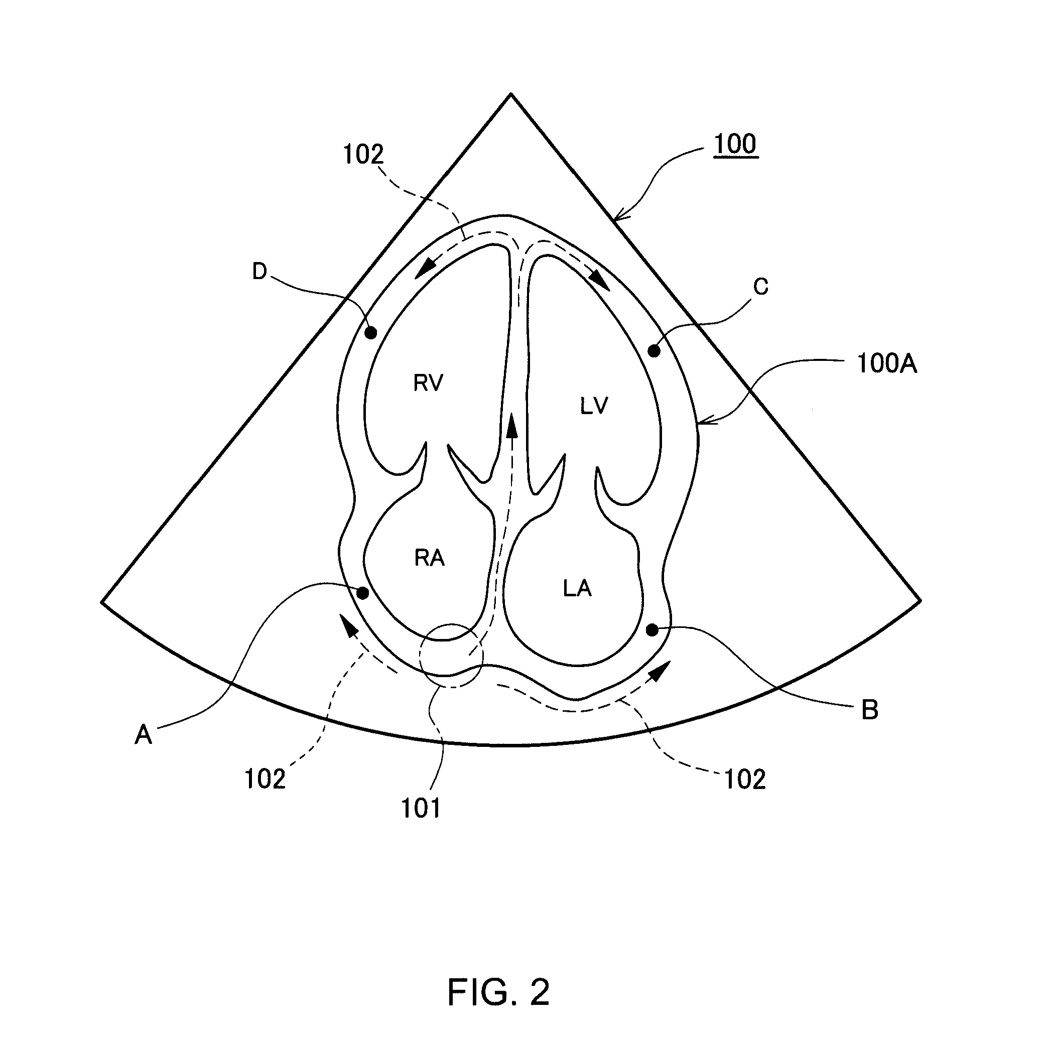
[0010]According to the above-described configuration of the present invention, on an ultrasonic image of the heart, a plurality of observation points are set on the conduction pathways of the heart, and each
observation point is tracked to determine the temporal displacement of each
observation point. For each observation point, a displacement waveform (that is, a displacement data array) is generated based on the temporal displacement each time. The plurality of displacement waveforms are analyzed on a common time axis, to calculate a time difference of motion caused among the plurality of observation points. The time difference of motion is provided to the user in a form of a numerical value, a graph, or the like. Based on such a time difference of motion, it becomes possible to objectively or quantitatively diagnose the conduction of the electric signal and the characteristic of cardiac muscle. This method is particularly desirably applied to the heart of a
fetus for which the electrocardiographic signal cannot be directly measured. If the heart function measurement can be realized as a diagnosis of a fetus before birth, it becomes possible to quickly and accurately prepare for the
disease of the heart of the fetus after birth, based on the measurement result. Therefore, the present invention provides a significant
advantage in the medical field.
[0011]The displacement measured as the result of the tracking may be a one-dimensional displacement, a two-dimensional displacement (two-dimensional displacement vector), or an absolute value of the two-dimensional displacement. Alternatively, the displacement may be a three-dimensional displacement. Alternatively, the displacement measuring direction may be individually determined for each observation point. Alternatively, the displacement measuring direction may be determined as a direction where each observation point is present, as viewed from a common reference point (for example, the center of gravity of the heart). In the measurement of the displacement, the displacement measuring direction is desirably determined such that a
translational motion component of the heart is cancelled or compensated for. For the tracking or displacement calculation of the observation point, there may be employed various known methods such as an inter-frame matching, an
ultrasonic Doppler method, and an echo tracking method which measures a
phase change. Desirably, the inter-frame matching is applied and a two-dimensional
motion vector between frames is calculated. The matching calculation may be executed between adjacent frames, or the matching calculation may be applied between a
reference frame and each subsequent frame. In either case, the motion of the observation point is successively observed. The plurality of observation points can be arbitrarily determined, but are desirably determined as points that are significant in the
disease diagnosis. The observation points may include points indicating sinus nodes corresponding to a source of the electric signal, or points near the sinus node. In either case, the time difference of motion is evaluated between a plurality of observation points. In this case, for example, the difference in timing of start of contraction is calculated. In general, it is desirable to determine an observation point proximal to the sinus node and an observation point distal from the sinus node.
[0012]According to another aspect of the present invention, it is desirable that, in the ultrasonic diagnostic apparatus, the plurality of observation points include a proximal observation point and a distal observation point, the plurality of displacement waveforms include a proximal displacement waveform corresponding to the proximal observation point and a distal displacement waveform corresponding to the distal observation point, and the analyzing unit calculates, as the time difference of motion, a relative
delay of the distal displacement waveform with respect to the proximal displacement waveform. The proximal observation point is a first observation point and the distal observation point is a second observation point. Alternatively, other observation points may be determined. A plurality of observation points in which the contraction motion is caused at the same temporal timing may be set, but desirably, two points including an upstream side site and a downstream side site in the electric signal conduction
system are determined as the observation points. Such two points are the proximal observation point and the distal observation point. “Proximal” and “distal” with regard to the two observation points refer to the temporal proximity, and do not necessarily correspond to proximity in the distance. It is expected that with the accumulation of future
clinical research using the present invention, more accurate observation points will be found.
[0013]According to another aspect of the present invention, it is preferable that, in the ultrasonic diagnostic apparatus, the analyzing unit comprises a first waveform analyzing unit which analyzes the proximal displacement waveform to identify a generation timing of local contraction caused by arrival of the electric signal as a proximal contraction timing, a second waveform analyzing unit which analyzes the distal displacement waveform to identify a generation timing of local contraction caused by arrival of the electric signal as a distal contraction timing, and a time analyzing unit which measures a time difference between the proximal contraction timing and the distal contraction timing to calculate the time difference of motion. In the analysis of each displacement waveform, a
representative point is identified for each
heartbeat. The
representative point is determined, for example, as a peak point, an inflection point, a zero-
cross point, etc., from the viewpoint of the
waveform analysis, and, desirably, a point representing the
muscle contraction start timing due to arrival of the electric signal or a timing corresponding to such a start timing is identified as the representative point.

