Method of manufacturing a pressure sensor

a manufacturing method and pressure sensor technology, applied in the field of pressure sensors, can solve the problems of affecting the ability of the detection system, affecting the heat detection capability of the system, and consuming a lot of time, and achieve the effect of easy and accurate etching

Active Publication Date: 2017-10-31
KIDDE TECH
View PDF19 Cites 0 Cited by
  • Summary
  • Abstract
  • Description
  • Claims
  • Application Information

AI Technical Summary

Benefits of technology

[0042]The diaphragm may be formed of any suitable material. The diaphragm may be formed of a material that provides an effective barrier to hydrogen (which may be evolved from

Problems solved by technology

Despite this improvement the manufacture of sensors with a consistently repeatable pressure set point is a relatively time consuming and potentially costly procedure.
This will have a detri

Method used


Image

  • Method of manufacturing a pressure sensor
  • Method of manufacturing a pressure sensor
  • Method of manufacturing a pressure sensor

Examples


Embodiment Construction

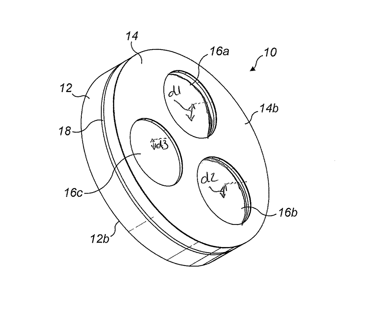
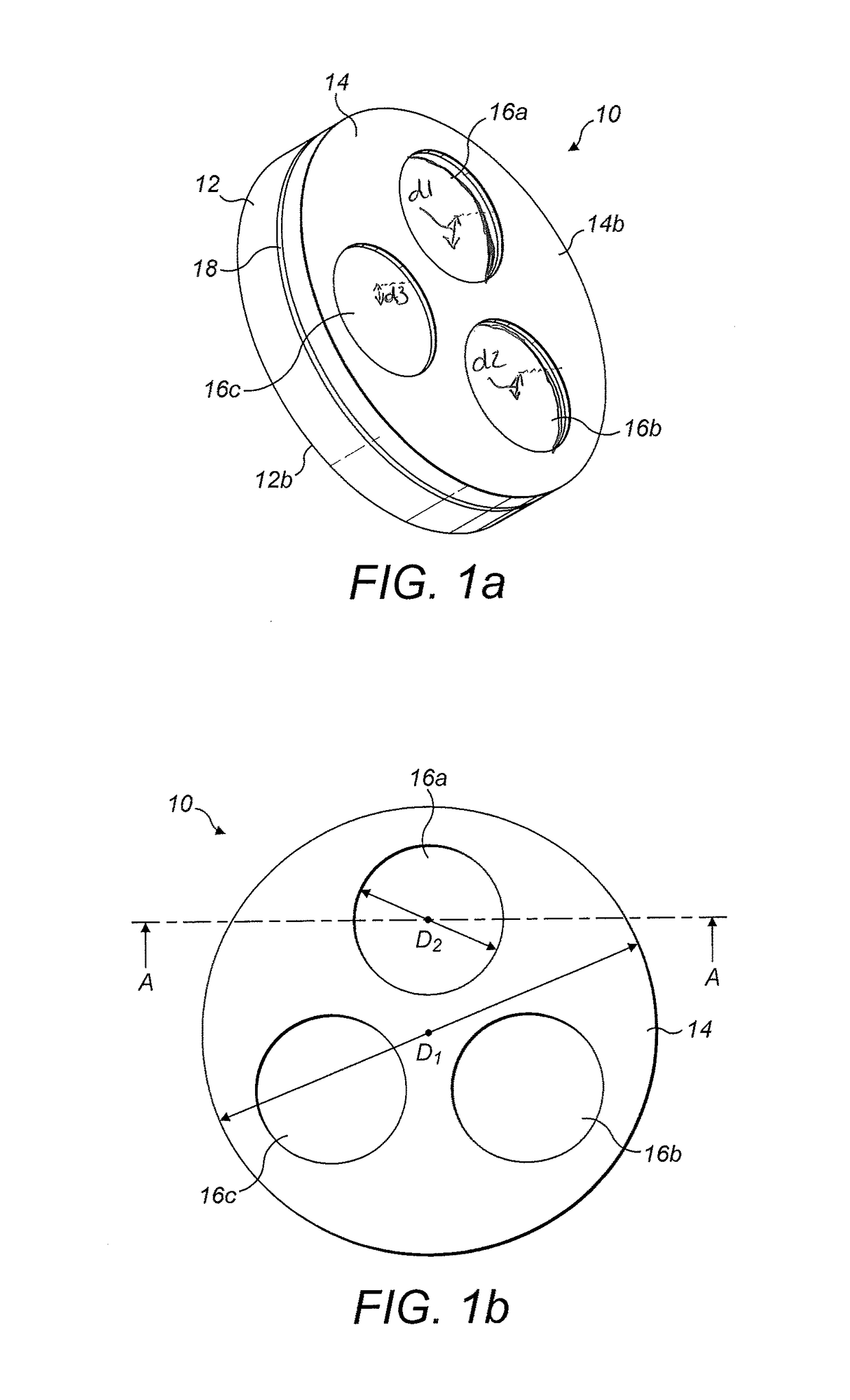
[0062]FIG. 1a shows a perspective view of an exemplary micromachined pressure sensor 10. The sensor 10 comprises a substrate 12 (‘first layer’) and a deformable diaphragm 14.

[0063]The diaphragm 14 may be formed of a ceramic material such as silicon nitride (Si3N4). The substrate 12 may be formed of a semiconductor such as silicon.

[0064]The diaphragm 14 comprises three recesses 16a, 16b, 16c in an upper (‘second’) surface 14b. The recesses 16a, 16b, 16c are circular and equally spaced.

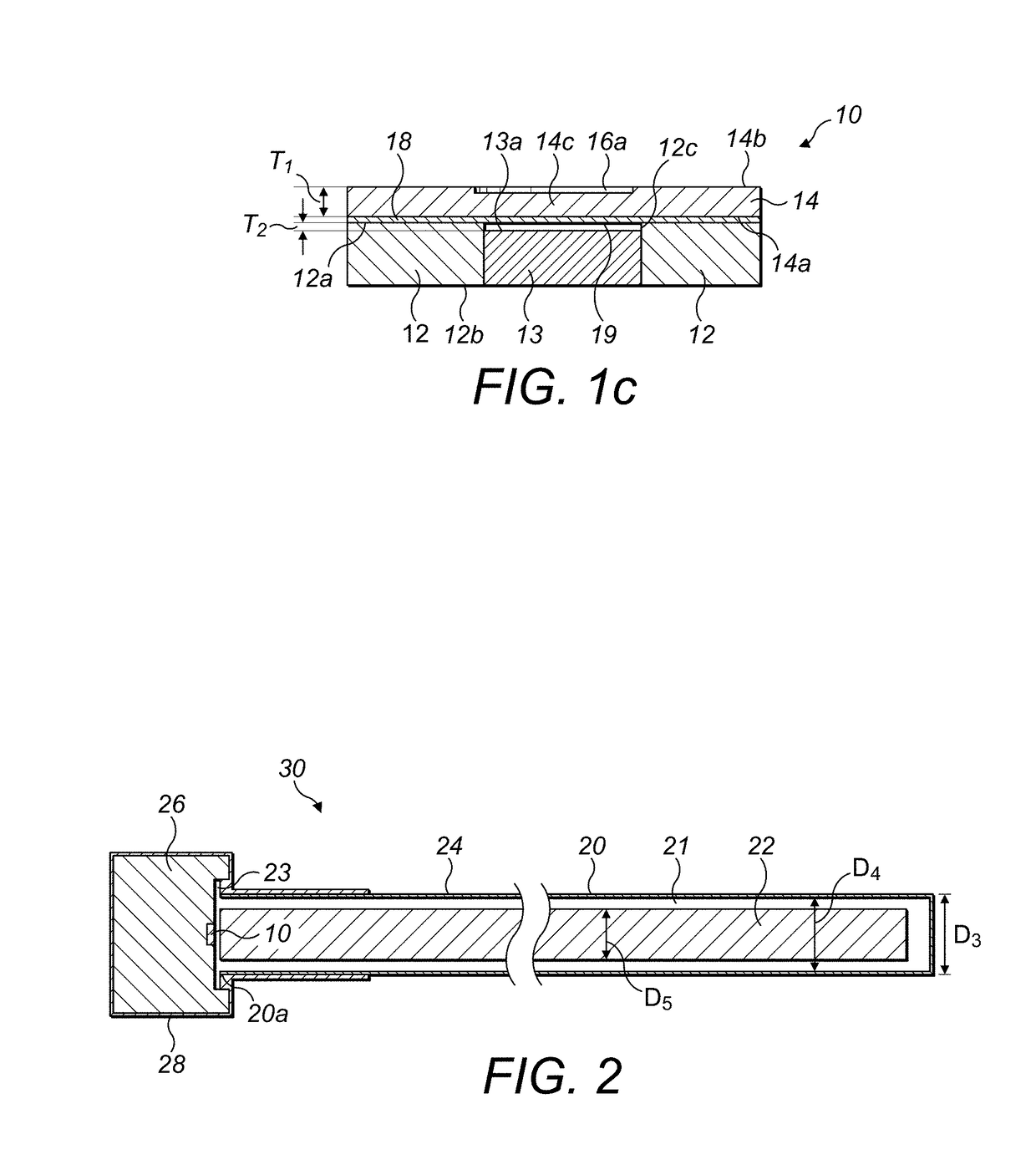
[0065]Located between diaphragm 14 and substrate 12 is an intervening electrically conductive, flexible metal layer 18. The metal layer 18 contacts the upper (‘first’) surface 12a of the substrate 12 and a lower (‘first’) surface 14a of diaphragm 14. The diaphragm 14, the substrate 12 and the intervening metal layer 18 are all circular and substantially the same size.

[0066]The diaphragm 14 and the intervening metal layer 18 may be formed via deposition. Features of the layers, such as recesses 16a, 16b,...


PUM

PropertyMeasurementUnit
Thicknessaaaaaaaaaa
Electrical conductivityaaaaaaaaaa
Flexibilityaaaaaaaaaa

Abstract

A method of manufacturing an overheat or fire alarm detection system, comprises the steps of micromachining a pressure sensor and securing a sensor tube in fluid communication with the pressure sensor. The sensor tube may comprise a hollow tube containing a material that evolves gas upon heating. The micromachining step may comprise doping at least a portion of a first layer, forming a cavity at least partially within the doped portion and forming a deformable diaphragm over the cavity.

Description

CROSS REFERENCE TO RELATED APPLICATIONS[0001]This application claims priority to GB Patent Application No. 1307802.7 filed Apr. 30, 2013, the entire contents of which are incorporated herein by reference.TECHNICAL FIELD[0002]The present disclosure relates to a pressure sensor for use in an overheat or fire alarm system and in particular to a method of manufacturing a sensor and such a system. Such overheat or fire alarm systems can be used to monitor a number of different environments including various parts of aircraft and other aerospace applications.BACKGROUND[0003]A known overheat or fire alarm system comprises a sensor tube in fluid communication with a pressure sensor, also known as a pressure switch module. The sensor tube commonly comprises a metallic sensor tube containing a metal hydride core, typically titanium hydride, and an inert gas fill, such as helium. Such a system is shown in U.S. Pat. No. 3,122,728 (Lindberg).[0004]Exposure of the sensor tube to a high temperatur...

Claims


Application Information

Patent Timeline
IPC IPC(8): G01L7/08G08B17/04G01L9/00
CPCG01L7/08G08B17/04G01L9/0042Y10T29/49004B81C1/00015B81C1/00349
Inventor RENNIE, PAULSMITH, PAUL D.
Owner KIDDE TECH
Why Eureka
Try Eureka