
Device delivery system

a delivery system and device technology, applied in the field of devices delivery systems, can solve the problems of long procedure time, coil protruding out of the vessel/malformation/aneurysm, and difficulty in navigation through tortuous anatomy

Active Publication Date: 2017-11-07
MICROVENTION INC
View PDF267 Cites 138 Cited by
  • Summary
  • Abstract
  • Description
  • Claims
  • Application Information

AI Technical Summary

Benefits of technology

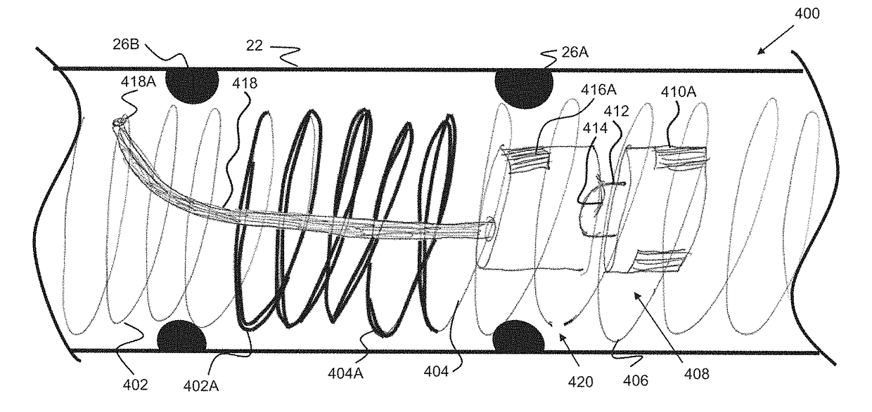
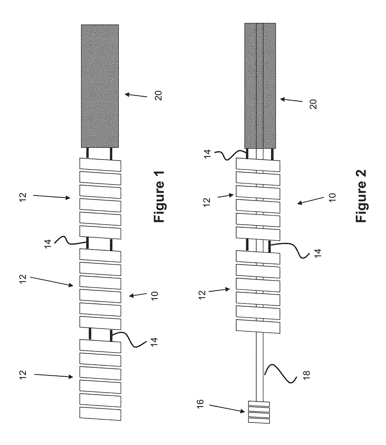
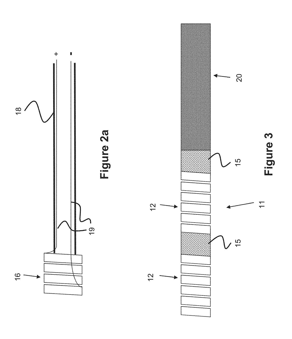
The patent describes how to create an embolic chain or coil that can be used to treat blockages in blood vessels. The chain or coil can be made by attaching multiple spheres to a thin wire and then detached by applying electric current to cause the wire to break. The chain or coil can be designed to release a drug or other material at the blockage site. In another embodiment, the chain or coil can be detached by using a power supply to electrolytically sever a joint outside of the catheter, which prevents any remaining joints from also degrading. This technology allows for more precise placement of the embolic device and better control over the delivery of the therapeutic material.

Problems solved by technology

If the coil is too short to sufficiently pack the vessel / malformation / aneurysm multiple coils may need to be introduced, which can lengthen procedure time.
If the coil is too long for the space there is a danger of the coil protruding out of the vessel / malformation / aneurysm.
Navigation through tortuous anatomy can be difficult.

Method used


Image

  • Device delivery system
  • Device delivery system
  • Device delivery system

Examples


Embodiment Construction

[0057]Specific embodiments of the invention will now be described with reference to the accompanying drawings. This invention may, however, be embodied in many different forms and should not be construed as limited to the embodiments set forth herein; rather, these embodiments are provided so that this disclosure will be thorough and complete, and will fully convey the scope of the invention to those skilled in the art. The terminology used in the detailed description of the embodiments illustrated in the accompanying drawings is not intended to be limiting of the invention. In the drawings, like numbers refer to like elements.

[0058]Unless otherwise defined, all terms (including technical and scientific terms) used herein have the same meaning as commonly understood by one of ordinary skill in the art to which this invention belongs. It will be further understood that terms, such as those defined in commonly used dictionaries, should be interpreted as having a meaning that is consis...


PUM


Abstract

A catheter system utilizing one or more sensors is described. The catheter can be used as part of an embolic coil system, guidewire system, or combined embolic coil / guidewire system where the devices interact with the catheter system. A variable detachment embolic coil system and guidewire system are also described.

Description

RELATED APPLICATIONS[0001]This application claims priority to U.S. Provisional Application Ser. No. 61 / 919,669 filed Dec. 20, 2013 entitled Device Delivery System, which is hereby incorporated herein by reference in its entirety.BACKGROUND OF THE INVENTION[0002]Vessel occlusion is often necessary in a variety of cases including but not limited to treatment of aneurysms, atrial septal defects, patent foramen ovale, left atrial appendage occlusion, patent ductus arteriosis, fistula, arterio-venous malformations, fallopian tube occlusion for the purposes of sterilization, and occlusion in the peripheral vasculature. One method of vessel occlusion involves filling the vessel or malformation or aneurysm with coils for the purposes of embolization. Such coils may be called embolic coils. Typical embolic coil technologies utilize a set length of coil so the coils may be introduced in various stages. If the coil is too short to sufficiently pack the vessel / malformation / aneurysm multiple coi...

Claims


Application Information

Patent Timeline
Patent Type & Authority Patents(United States)
IPC IPC(8): A61B17/12A61M25/01A61M25/09A61B17/00
CPCA61M25/0138A61B17/1214A61B17/12163A61M25/09041A61M25/0158A61B2017/1209A61B2017/12054A61B2017/12063A61B2017/12068A61B2017/00115
Inventor BOWMAN, HEATHTSUKASHIMA, ROSS
Owner MICROVENTION INC
Learn More