
Extracting an embedded DC signal to provide a reference voltage for an optical receiver

a technology of optical receiver and reference voltage, applied in the direction of electromagnetic transmission, electrical equipment, transmission, etc., can solve the problems of high-performance optical, difficult to design and verify the feedback loop, and the dc signal level embedded in the photocurrent can change rapidly

Active Publication Date: 2017-11-14
ORACLE INT CORP
View PDF9 Cites 5 Cited by
  • Summary
  • Abstract
  • Description
  • Claims
  • Application Information

AI Technical Summary

Benefits of technology

The feedback connection helps to stabilize the output of the low-speed high-gain amplifier at a specific point.

Problems solved by technology

The development of high-performance optical receivers presents a number of design challenges.
However, this is a challenging task, because due to operational constraints, such as limited physical channel bandwidth and data density, the DC signal level embedded in the photocurrent can change rapidly.
This traditional approach has a number of problems.
(1) It is difficult to design and verify the feedback loop due to the complex dynamic behavior of the multiple high-speed gain stages.
(2) Instability in the feedback loop limits the receiver sensitivity.
(More specifically, oscillations caused by the dynamic behavior of the high-speed gain stages can hurt the sensitivity of the optical receiver and can also increase jitter and bit error rate (BER)).
(3) Finally, the receiver switching time between low-power (sleep) mode and high-power (operating) mode is quite long because it cannot be smaller than the settling time of the feedback loop.

Method used


Image

  • Extracting an embedded DC signal to provide a reference voltage for an optical receiver
  • Extracting an embedded DC signal to provide a reference voltage for an optical receiver
  • Extracting an embedded DC signal to provide a reference voltage for an optical receiver

Examples


Embodiment Construction

[0022]The following description is presented to enable any person skilled in the art to make and use the present embodiments, and is provided in the context of a particular application and its requirements. Various modifications to the disclosed embodiments will be readily apparent to those skilled in the art, and the general principles defined herein may be applied to other embodiments and applications without departing from the spirit and scope of the present embodiments. Thus, the present embodiments are not limited to the embodiments shown, but are to be accorded the widest scope consistent with the principles and features disclosed herein.

[0023]The data structures and code described in this detailed description are typically stored on a computer-readable storage medium, which may be any device or medium that can store code and / or data for use by a computer system. The computer-readable storage medium includes, but is not limited to, volatile memory, non-volatile memory, magneti...


PUM


Abstract

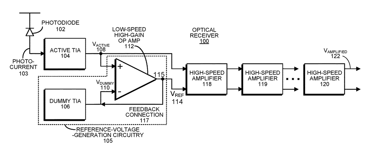
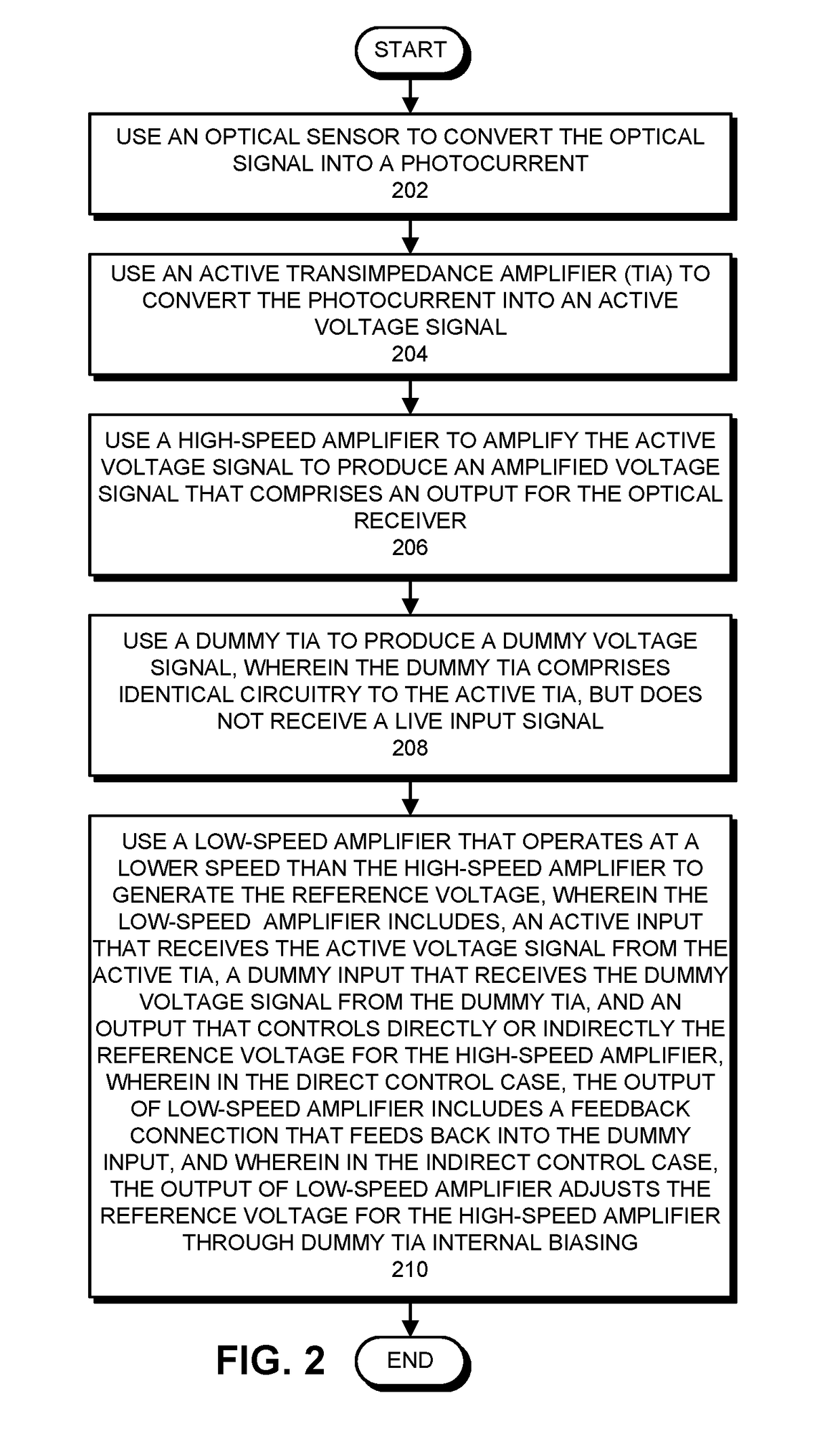
An optical receiver includes: an active transimpedance amplifier (TIA) that converts a photocurrent from a photosensor into an active voltage signal; a high-speed amplifier that amplifies the active voltage signal to produce an amplified voltage signal that comprises an output for the optical receiver; and a reference-voltage-generation circuit that generates a reference voltage for the high-speed amplifier. This reference-voltage-generation circuit includes a dummy TIA that is identical to the active TIA, but does not receive a live input signal, and produces a dummy voltage signal. It also includes a low-speed amplifier which includes: an active input that receives the active voltage signal from the active TIA output; a dummy input that receives the dummy voltage signal from the dummy TIA output; and an output that controls directly or indirectly the reference voltage for the high-speed amplifier. In the direct control case, the output of low-speed amplifier includes a feedback connection that feeds back into the dummy input. In the indirect control case, the output of low-speed amplifier adjusts the reference voltage for the high-speed amplifier through dummy TIA internal biasing.

Description

BACKGROUND[0001]Field[0002]The disclosed embodiments relate to the design of an optical receiver. More specifically, the disclosed embodiments relate to the design of an optical receiver which extracts an embedded DC signal level from a photocurrent input to provide a reference voltage for the optical receiver.[0003]Related Art[0004]Silicon photonics is a promising new technology that can potentially provide large communication bandwidth, low latency and low power consumption for inter-chip and intra-chip communications. In order to achieve low-latency, high-bandwidth optical connectivity, designs for a variety of optical components need to be developed, including: optical modulators, optical multiplexers / demultiplexers and optical receivers.[0005]The development of high-performance optical receivers presents a number of design challenges. During operation, an optical receiver obtains a photocurrent from a photo detector, and converts it into an amplified voltage signal. During this...

Claims


Application Information

Patent Timeline
Patent Type & Authority Patents(United States)
IPC IPC(8): H04B10/69
CPCH04B10/691H04B10/693
Inventor XIE, JINGQIONGKRISHNAMOORTHY, ASHOK V.ZHENG, XUEZHEDENQ, JEFFREY W.RAJ, KANNANCUNNINGHAM, JOHN E.THACKER, HIREN D.
Owner ORACLE INT CORP
Learn More