Supercharge Your Innovation With Domain-Expert AI Agents!

Self-equalizing photo detector

a photo detector and self-equalization technology, applied in the field of self-equalization photo detectors, can solve the problems of moving communication speed bottleneck, limiting the data rate of such cables, and the implementation cost of optical communication channels remains an impedimen

Active Publication Date: 2017-11-28
CALIFORNIA INST OF TECH
View PDF3 Cites 3 Cited by
  • Summary
  • Abstract
  • Description
  • Claims
  • Application Information

AI Technical Summary

Benefits of technology

The present invention relates to a detector and method for equalizing signals. The detector includes a pair of optical splitters, an optical delay element, and a pair of photo detectors. The optical splitters are adjustable to control the amount of optical power. The method involves splitting an optical signal into multiple optical signals, delaying one of the signals, and combining the signals to generate an equalized signal. The detector and method can be used in various applications such as optical communication systems.

Problems solved by technology

Despite advances in co-integration of electronics and photonics on the same substrate in silicon substrate, the implementation cost of optical communication channels remains an impediment to broad deployment of high speed optical systems for short range front-end of communication networks.
The main bottleneck limiting the data rate in such cables is the bandwidth of the electro-optical components, such as the optical modulator and photodiodes.
As a result, the communication speed bottleneck is moving from communication channel to the electro-optical interfaces.
While integrated electronic circuits continue to operate at higher speeds, they still face challenges in keeping up with the bandwidth required for equalization.

Method used


Image

  • Self-equalizing photo detector
  • Self-equalizing photo detector
  • Self-equalizing photo detector

Examples


Embodiment Construction

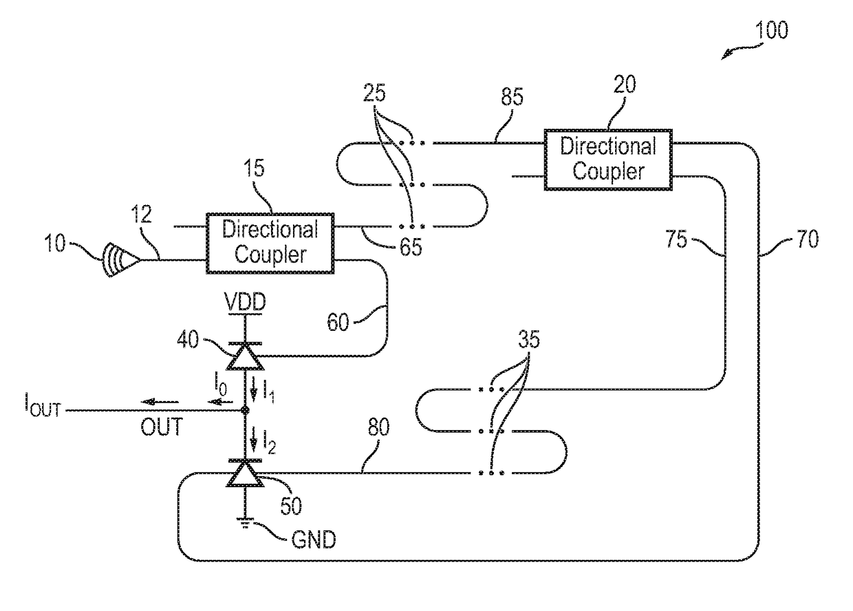
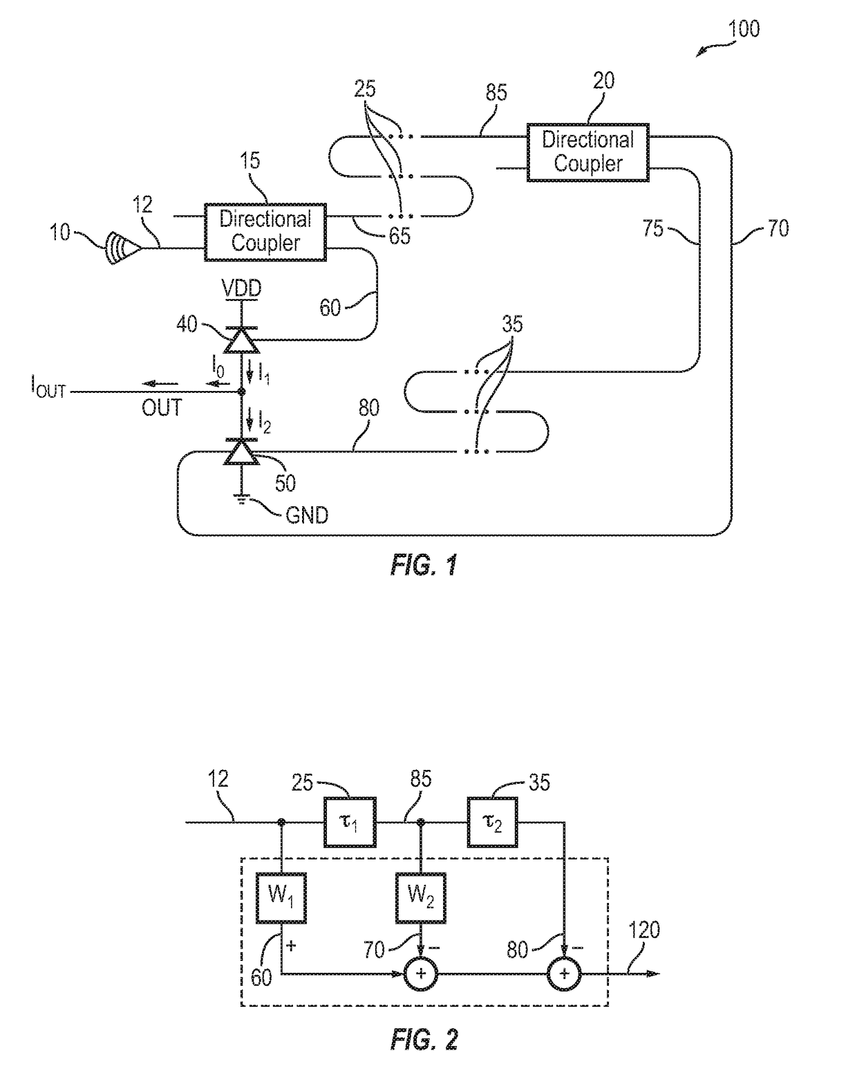
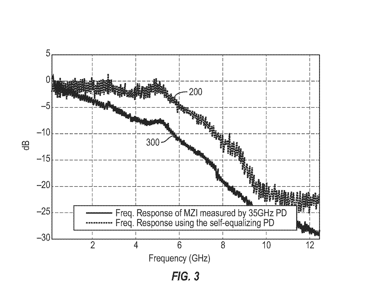
[0038]An equalizer, in accordance with one embodiment of the present invention, operates as a high-pass filter to cancel out channel (link) attenuations at relatively high frequencies. The high-pass filter may be disposed anywhere in the channel, such as in the transmitter or receiver, or implemented through digital signal processing. In optical links, such high pass filter may be implemented using electro-optical components available in a typical silicon photonics process.

[0039]An electro-optical equalizer, in accordance with embodiments of the present invention, benefits from the high optical bandwidth and thus achieves more enhanced equalization than conventional equalizers that use only electrical components. The electrical components used in an electro-optical equalizer, in accordance with the present invention, eliminate the strong wavelength dependence of the narrowband grating-based equalizers. The equalizer substantially improves the incoming optical signal directly before ...


PUM


Abstract

A self-equalizing photo-detector (SEPD) includes, in part, a multitude of optical splitters and photo detectors, and at least one optical delay element. The first optical splitter splits an optical signal into second and third optical signals. The optical delay element delays the second optical signal to generate a fourth optical signal. The second optical splitter splits a signal representative of the fourth optical signal to generate fifth and sixth optical signals. The first photo detector receives the third optical signal via a first optical path, has an anode terminal coupled to an output terminal of the detector and a cathode terminal coupled to a first supply voltage. The second photo detector receives the sixth optical signal via a second optical path, has an anode terminal coupled to a second supply voltage and a cathode terminal coupled to the output terminal of the detector.

Description

CROSS-REFERENCES TO RELATED APPLICATIONS[0001]The present application claims benefit under 35 USC 119 (e) of U.S. provisional Application No. 62 / 000,413, filed May 19, 2014, entitled “Self-Equalizing Photo Detector”, and U.S. provisional Application No. 62 / 065,240, filed Oct. 17, 2014, entitled “Adjustable Self-Equalizing Photo Detector”, the contents of which are incorporated herein by reference in their entirety.BACKGROUND OF THE INVENTION[0002]Despite advances in co-integration of electronics and photonics on the same substrate in silicon substrate, the implementation cost of optical communication channels remains an impediment to broad deployment of high speed optical systems for short range front-end of communication networks.[0003]Active optical cables have become widely available in data centers and high performance computing clusters. The main bottleneck limiting the data rate in such cables is the bandwidth of the electro-optical components, such as the optical modulator an...

Claims


Application Information

Patent Timeline
Patent Type & Authority Patents(United States)
IPC IPC(8): G02B6/26H04B10/67G02B6/293G02B6/28
CPCH04B10/671G02B6/29352G02B6/2861G02B6/2935
Inventor ABIRI, BEHROOZHAJIMIRI, SEYED ALIAFLATOUNI, FIROOZZHOU, ANDY
Owner CALIFORNIA INST OF TECH
Features
  • R&D
  • Intellectual Property
  • Life Sciences
  • Materials
  • Tech Scout
  • Unparalleled Data Quality
  • Higher Quality Content
  • 60% Fewer Hallucinations
Learn More