Multiple wavelengths real time phase shift interference microscopy

a phase shift interference microscopy and multi-wavelength technology, applied in the field of optical imaging, can solve the problems of serious slowdown of industrial rapid process control procedures, inability to image dynamically changing scenes without producing serious errors, and inability to introduce errors

Active Publication Date: 2018-01-30
PHOTONICSYS
View PDF9 Cites 20 Cited by
  • Summary
  • Abstract
  • Description
  • Claims
  • Application Information

AI Technical Summary

Benefits of technology

[0028]d) a process and control unit that is connected to and controls the three detectors, the process and control unit comprising software algorithms adapted to carry out a calibration procedure from known phase shifts, which is used to determine the deviations from ideality of the optical phase components and to extract correct interferometric signals and correct object heights.

Problems solved by technology

There are several problems with the standard phase shift approach.
First, as PSI is a very sensitive technique with sensitivity in the nanometer (nm) range, the fact that the phase shifted signals are grabbed successively and not simultaneously might introduce an error if the interferometer is not super stable during the successive phase shifted measurements.
Second, dynamically changing scenes cannot be imaged without producing serious errors since the phase shifting requires time.
Third, industrial rapid process control procedures are seriously slowed down because for each frame of the sample field four (minimum three) snapshots must be made in order to extract the phase.
Obviously, this limits the technique to samples with height variations of only several hundreds of nanometers while the majority of applications require the ability to image samples with height variations of several micrometers.
In the past, many researchers concentrated on phase unwrapping algorithms [3-9] which provide partial solution for samples with overall height variations larger than one fringe; however, these algorithms are often likely to collapse if the sample is with large steps, discontinuities or too large speckle noise.
However, to the best of the inventors' knowledge none of the preceding works demonstrated simultaneous PSI using only three CCDs.
Moreover, none of the preceding works demonstrated multi wavelengths simultaneous PSI.
In addition none of the preceding works demonstrated a three wavelengths calibration procedure to correct for the non-idealities of the optical phase components used.

Method used


Image

  • Multiple wavelengths real time phase shift interference microscopy
  • Multiple wavelengths real time phase shift interference microscopy
  • Multiple wavelengths real time phase shift interference microscopy

Examples


Embodiment Construction

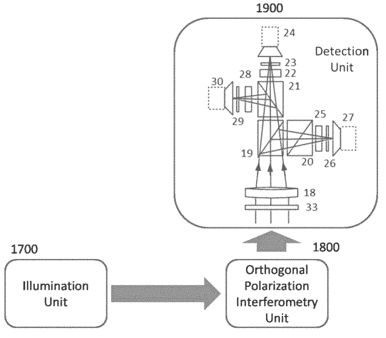
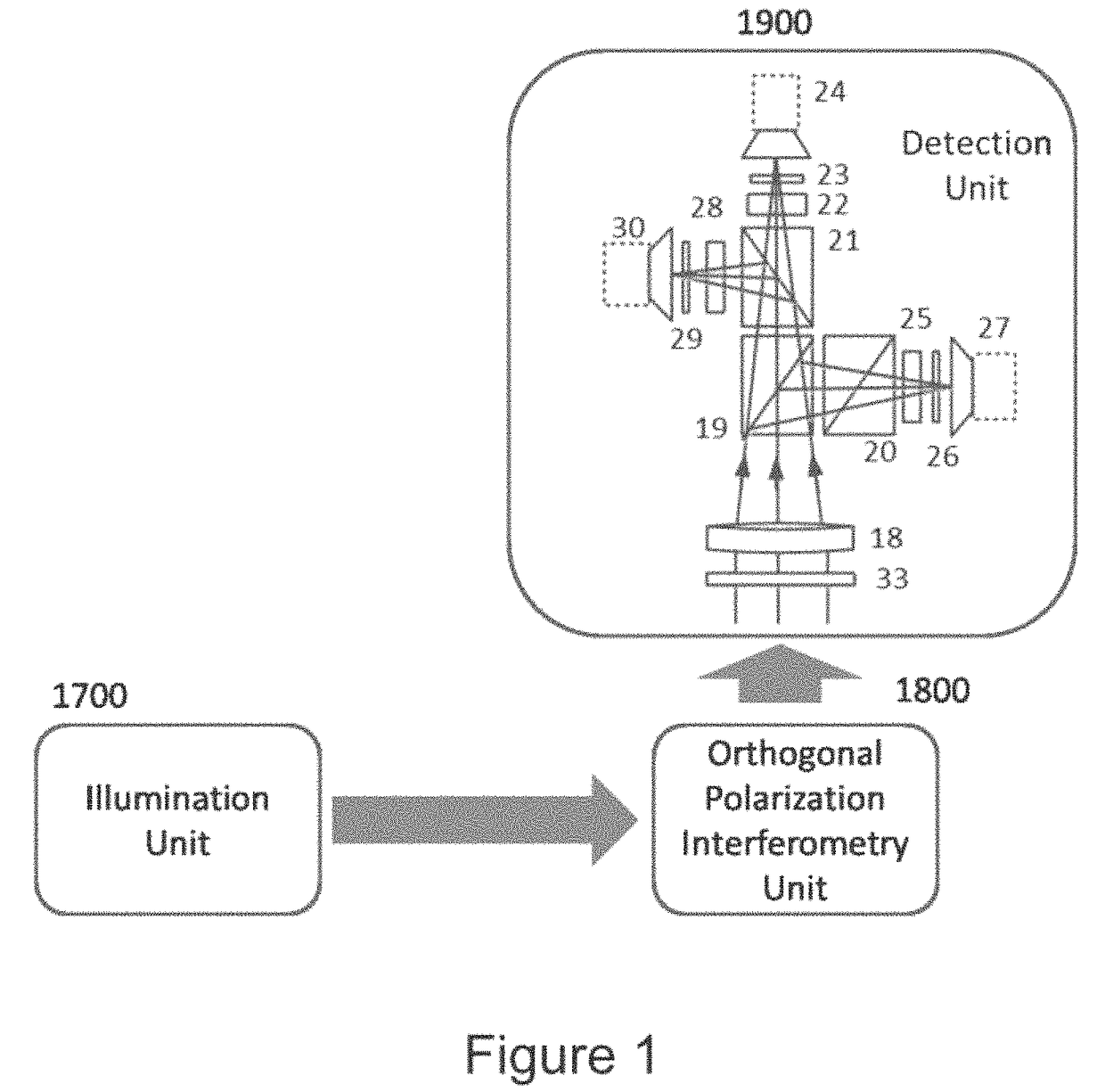
[0044]The invention is a system and method that enable obtaining high resolution 3D images in a single shot.

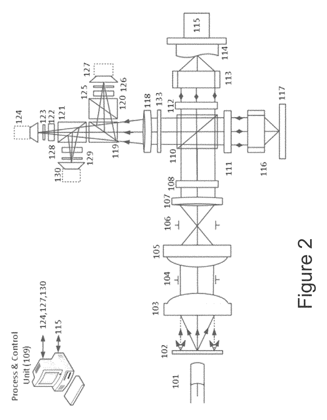
[0045]The system is an ultra-high speed, real time multi wavelength phase shift interference microscopy system that uses three synchronized color CCD cameras. Each CCD is equipped with a precision achromatic phase mask which in turn allows obtaining π / 2 phase shifted signals in three different wavelengths simultaneously. The combination of simultaneous phase shifts at different wavelengths allows overcoming all the above mentioned problems of the prior art. In comparison with the methods using pixelated phase mask CCD [15-16] or the frequency domain (FD) real time techniques [3-4] that are sometimes combined with color CCD [17-18], the method described herein is less limited to high spatial variations of the sample; FD techniques require that the carrier frequency induced by the tilting of the reference mirror is higher than the sample spatial bandwidth—a requirement that can ...


PUM


Abstract

A system microscopy system and method that enable obtaining high resolution 3D images in a single shot are presented. The system is an ultra-high speed, real time multi wavelength phase shift interference microscopy system that uses three synchronized color CCD cameras. Each CCD is equipped with a precision achromatic phase mask which in turn allows obtaining π/2 phase shifted signals in three different wavelengths simultaneously.

Description

FIELD OF THE INVENTION[0001]The invention is from the field of optical imaging. In particular the invention is from the field of real time high resolution three dimensional imaging.BACKGROUND OF THE INVENTION[0002]Publications and other reference materials referred to herein are numerically referenced in the following text and respectively grouped in the appended Bibliography which immediately precedes the claims.[0003]Phase shift interferometry (PSI) [1] is a well-established optical technology that allows high resolution non-contact three dimensional (3D) topographical measurements of objects. In PSI the 3D topography is obtained by using the interference signal phase values from each point of the surface of the object. As the phase is packed within the interference signal, there is a need to extract the phase. The standard approach to extract the phase from the interference signal is by changing the reference arm length of the interferometer of the PSI system in four (minimum thr...

Claims


Application Information

Patent Timeline
Patent Type & Authority Patents(United States)
IPC IPC(8): G07B9/02G02B21/00G02B27/28G02B21/36G02B21/22G02B21/26
CPCG02B21/0056G02B21/0092G02B21/0064G02B27/286G02B21/0084G02B21/365G02B21/22G02B21/0032G02B21/26G01B11/2441G01J1/00G02B21/367
Inventor SAFRANI, AVNERNEY, MICHAELABDULHALIM, IBRAHIM
Owner PHOTONICSYS
Why Eureka
Try Eureka