Vibration-proof structure of rotating body

a technology of rotating body and vibration-proof structure, which is applied in the direction of grinding machine components, mechanical equipment, manufacturing tools, etc., can solve the problems of reducing machining precision and quickly dissipating energy, and achieve the effect of enhancing the vibration-absorbing function of the rotating body

Active Publication Date: 2018-02-13
DAISHOWA SEIKI CO LTD
View PDF16 Cites 4 Cited by
  • Summary
  • Abstract
  • Description
  • Claims
  • Application Information

AI Technical Summary

Benefits of technology

[0013]With the above-described arrangement of causing a boundary position between the shaft members and a boundary position of the tubular members to be different from each other, tendency of mutual movement in the radial direction between the shaft members or between the tubular members due to rotational vibration can be effectively suppressed by a tubular member opposed to the boundary position between the shaft members or by a shaft member opposed to the boundary position between the tubular members.
[0014]For instance, when relative movement tends to occur between the shaft members adjacent each other in the longitudinal direction, firstly, either one shaft member will press a tubular member disposed on its outer side. Yet, movement of this pressed tubular member will be checked by the other shaft member. Therefore, the relative movement between the adjacent shaft members will be suppressed as a result. In this, the relative position between the shaft member and the tubular member will change slightly, thus causing friction between these members. And, this friction serves to effectively absorb the vibration of the rotating body.
[0016]With the above-described arrangement of setting the total number of the tubular members smaller than the total number of the shaft members, it becomes easier to set a length of at least one tubular member longer than a length of any one of the shaft members. An object is subject to an inertial movement of a rotation system. And, its magnitude increases in direct proportion to the mass of the object and square of the radius of rotation. Therefore, by increasing the length of the tubular member which is disposed on the outside of the rotation radius, it becomes possible to increase the mass of the tubular member and the inertial moment, thereby to improve the stability of rotation. On the other hand, the rotation radius of the shaft member disposed on the inner side is small and its length in the longitudinal direction is also short. Therefore, the inertial moment is kept small. In this way, by providing a difference between the inertial moment of the shaft member and the inertial moment of the tubular member, it becomes possible to allow a relative movement between the shaft member and the tubular member to occur positively when vibration occurs in the rotating body, thereby to increase the friction occurring between these members for more effective absorption of the rotating body.
[0018]With the above-described arrangement of disposing an elastic seal between the shaft members and the tubular members, when vibration occurs in the rotating body, displacement of the shaft members is transmitted to the tubular members via the elastic seal, and movement of the shaft members is limited by the rotational inertia of the tubular members. With this, vibration of the rotating body can be reduced.
[0022]With the above-described arrangement, the mass of the tubular member is increased relative to the mass of the shaft member. With this, the inertial moment of the tubular member is increased, so that the rotational state of the tubular member is stabilized. As a result, the vibration absorbing function of the rotating body can be enhanced.
[0024]When vibration occurs in the rotating body such as a tool holder, the amount of displacement is larger at the center position in the longitudinal direction. With the above-described arrangement, three tubular members are provided as a set and the radial thickness of the tubular member disposed at the center in the longitudinal direction is set greater than the radial thickness of the other tubular members. With this, the inertial moment of the tubular member disposed at such center region is increased, so that the vibration absorbing function of the rotating body can be enhanced.

Problems solved by technology

Such device suffers a problem that when the blade portion on the leading end side comes into contact with a work, the tool holder is bent and deformed to cause vibration in the tool holder, thus leading to reduction in machining precision.
In the course of this, slight displacement will occur between the adjacent cylindrical members, thus causing friction between the multiple-layered members, which will dissipate the energy quickly.

Method used


Image

  • Vibration-proof structure of rotating body
  • Vibration-proof structure of rotating body
  • Vibration-proof structure of rotating body

Examples


first embodiment

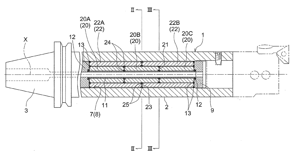
[0033]FIGS. 1 through 3 show a tool holder 1 (an example of “a rotating body”) having a vibration-proof structure according to the present invention.

[0034]This tool holder 1 is for a boring machining operation and includes a cylindrical elongate main body 2 to which a tool is attached, and a tapered shank portion 3 to be gripped to a spindle (not shown) of a machine tool.

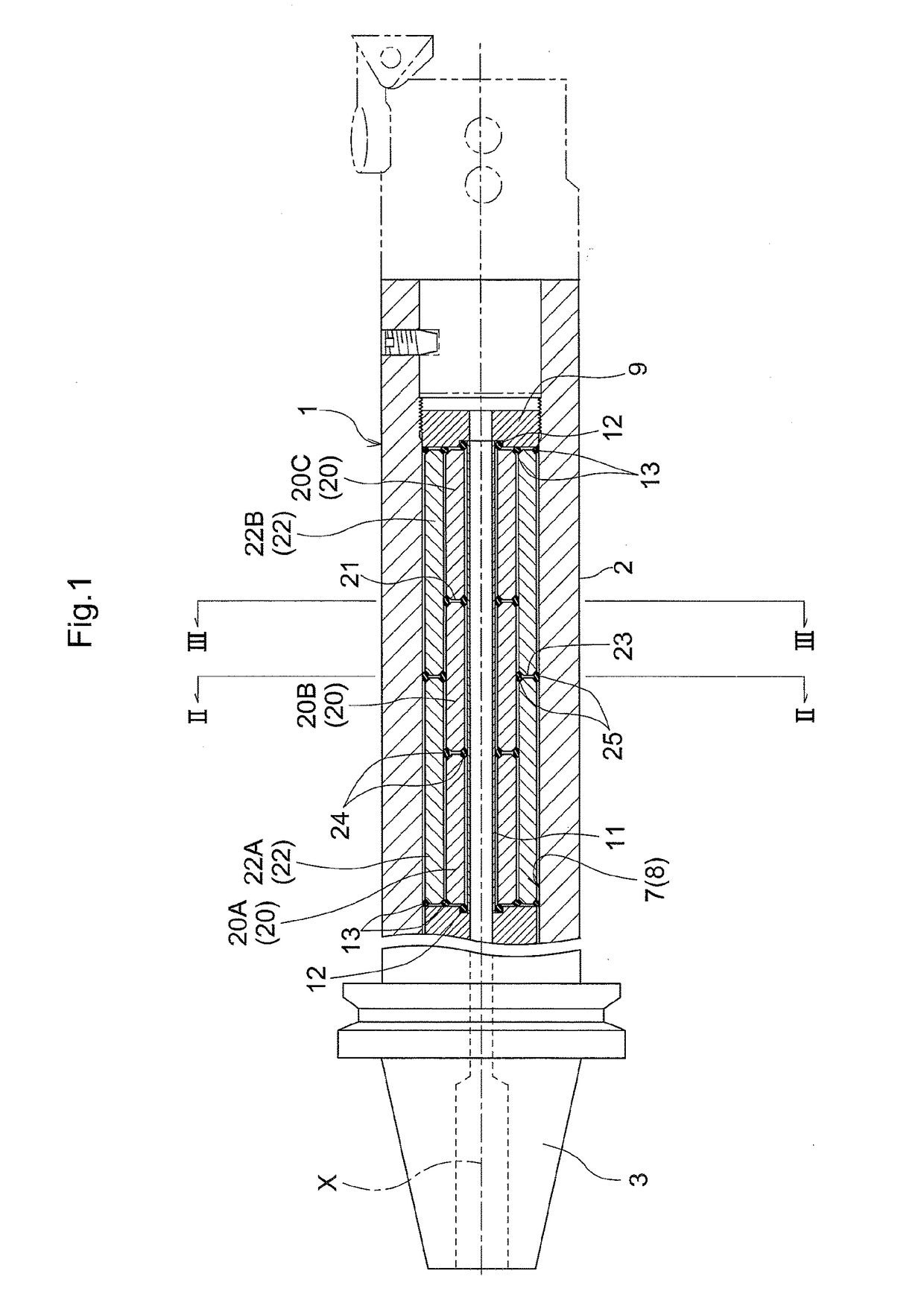
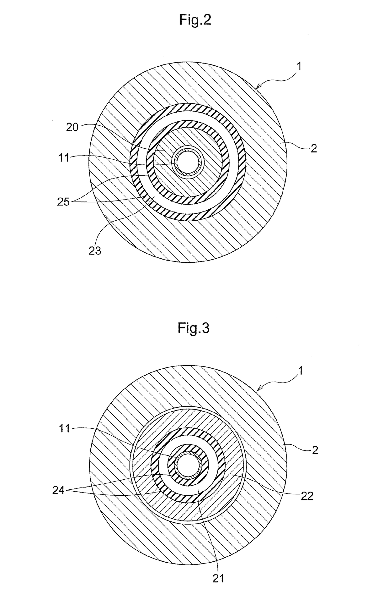
[0035]The main body 2 includes therein a cylindrical hollow portion 7. This hollow portion 7 is formed by a shaft hole 8 which opens wide toward the leading end of the main body 2. In the shaft hole 8, a coolant pipe 11, shaft members 20 and tubular members 22 are disposed coaxially in the order from the center side of the hole.

[0036]On the outer circumference side of the coolant pipe 11, a plurality of cylindrical shaft members 20 are arranged along a longitudinal direction of a rotation axis X. FIG. 1 shows an example wherein three such shaft members 20 are disposed. On further outer side of the shaft members 20, ...

second embodiment

[0047]A second embodiment of the present invention is shown in FIG. 4. Here, a radial thickness of the tubular member 22 is set greater than a radial thickness of the shaft member 20. With this arrangement, the mass of the tubular member 22 is increased relative to the mass of the shaft member 20. Therefore, the inertial moment of the tubular member 22 is increased, so that the rotational state of the tubular member 22 is stabilized. As a result, the vibration absorbing function of the tool holder 1 is increased.

third embodiment

[0048]In this embodiment, as shown in FIG. 5, four shaft members 20 having an equal length a in the longitudinal direction are disposed and also on the outer side thereof, three tubular members 22 of an equal length are disposed. Here, the thickness of the tubular member 22B disposed centrally of the tubular members 22 is set greater than the thickness of the other tubular members 22A, 22C. As for the shaft members 20, the members 20A, 20D disposed at the extreme ends have a same thickness, whereas the center (intermediate) members 20B, 20C have a thickness which decreases at the center side in the longitudinal direction.

[0049]When vibration occurs in the tool holder 1, the amount of displacement will be larger at the longitudinal center position. Therefore, the vibration absorbing function is enhanced by the increase of the inertial moment of the tubular member 22B disposed in this region.


PUM


Abstract

Provided is a vibration-proof structure capable of more effectively reducing rotational vibration of a rotating body during a cutting operation. According to a configuration of the structure, inside a main body of the rotating body, there are provided a plurality of shaft members arranged along a longitudinal direction of a rotation axis of the rotating body and at least one layer of multiple tubular members fitted over the shaft members and arranged coaxially with the rotation axis along the longitudinal direction of this rotation axis; and a boundary position between the shaft members adjacent each other in the longitudinal direction and a boundary position between the tubular members adjacent each other in the longitudinal direction are set as different positions along the longitudinal direction.

Description

TECHNICAL FIELD[0001]The present invention relates to a vibration-proof structure of a rotating body which prevents vibration at the time of a rotary machining operation.BACKGROUND ART[0002]Conventionally, as a device for cutting a work formed of a metal or the like, there is known a device configured to hold an end portion side of a tool holder with a cutting blade portion fixed to its leading end and to rotate this tool holder. Such device suffers a problem that when the blade portion on the leading end side comes into contact with a work, the tool holder is bent and deformed to cause vibration in the tool holder, thus leading to reduction in machining precision. Such vibration differs in its mode, depending on the length or outer dimensions of the tool holder or property of material constituting the tool holder, etc.[0003]For this reason, e.g. Patent Document 1 shows a case in which for obtaining a large damping ratio for a wide range of vibration frequency, a boring bar for use ...

Claims


Application Information

Patent Timeline
Patent Type & Authority Patents(United States)
IPC IPC(8): B23B27/00B23B29/02B23C5/00B23Q11/00
CPCB23B29/022B23B27/002B23B2229/00B23B2250/04B23Q11/0039B23B2251/70B23C5/003B23D2277/10B23Q11/0032B23B2250/16B24B41/007F16F15/08F16F15/1201B23B29/02B23C9/00F16F15/126
Inventor NAKATANI, JOJIISHIDA, YASUYUKI
Owner DAISHOWA SEIKI CO LTD
Why Eureka
Try Eureka