Sorting two-dimensional nanomaterials by thickness

a two-dimensional nanomaterial and nano-material technology, applied in the direction of graphene nanoribbons, single-layer graphene, centrifugal force sediment separation, etc., can solve the problems of difficult position control, inability to provide thickness control, and considerable location effort, so as to improve separation quality, improve separation quality, and improve separation fractions. enriched

Active Publication Date: 2018-02-13
NORTHWESTERN UNIV
View PDF19 Cites 3 Cited by
  • Summary
  • Abstract
  • Description
  • Claims
  • Application Information

AI Technical Summary

Benefits of technology

[0010]In one aspect, the present teachings can be directed to sorting two-dimensional (planar) nanomaterials by atomic layer thickness. Specifically, a polydisperse population of planar nanomaterials which is polydisperse at least with respect to thickness can be first contacted with one or more surface active components to provide a nanomaterial composition. In various embodiments, the nanomaterial composition is a stable dispersion of the nanomaterials in water, in which the nanomaterials are dispersed effectively by the one or more surface active components. The one or more surface active components can be selected for their ability to associate differentially with the nanomaterials of different thickness such that individual nanomaterial crystallite or flake of different thickness, upon association with the surface active components, can exhibit different buoyant densities in a fluid medium. Separation by buoyant density subsequently can be accomplished by, but is not limited to, density gradient ultracentrifugation, after which physically separated nanomaterials, grouped according to atomic layer thickness, can be recovered.
[0013]A single separation cycle according to the present methods often leads to enrichment that is satisfactory for most applications. Accordingly, following one separation cycle, one or more separation fractions can be collected from the density gradient and used for various applications. However, performing one or more additional sorting or separation cycles can improve the quality of the separation and provide increasingly enriched separation fractions.
[0014]In another aspect, the present teachings relate to producing aqueous dispersions of two-dimensional (planar) hydrophobic nanomaterials. In contrast to the prior art, the present teachings provide stable aqueous dispersions of two-dimensional hydrophobic nanomaterials without chemical modification such as oxidation. Instead, stable aqueous dispersions are obtained by providing the hydrophobic nanomaterials in composition with one or more surface active components described herein, in particular, surface active components having one or more planar organic groups. Without wishing to be bound by any particular theory, it is believed that one or more surface active components described herein can encapsulate individual flakes of nanomaterials and allow a large amount of the nanomaterials to be effectively dispersed in water. For example, aqueous dispersions having a minimum concentration of 40 μg / mL of nanomaterials according to the present teachings can remain stable for weeks without visible aggregation.

Problems solved by technology

Despite the technological potential of two-dimensional nanomaterials, methods of synthesizing and purifying them are in their infancy.
First, it is difficult to control the position at which crystallites will be placed; consequently, considerable effort is required to locate them.
Second, cleavage does not provide control over the thickness of flakes produced, resulting in a limited number of atomically thin crystallites with the majority being tens of nanometers thick.
Third, the prospects for large scale production of graphene and other crystallites through micromechanical cleavage are unfavorable.
However, while these epitaxial graphene samples have the benefit of spanning large areas, full control over the thickness of the resulting crystallites remains a challenge.
Yet, because of the often violent reactions between the intercalation compounds and water or other solvents, the resulting crystallites usually are at least partially oxidized or otherwise have defect sites which impair their properties (see Li et al., Science, 319, 1229 (2008)).
Furthermore, while it is possible to generate monolayer graphene oxide by ensuring that graphite is sufficiently oxidized, it is unlikely that bilayer graphene oxide (or n-layer graphene oxide) could be formed preferentially through controlled oxidation.

Method used


Image

  • Sorting two-dimensional nanomaterials by thickness
  • Sorting two-dimensional nanomaterials by thickness
  • Sorting two-dimensional nanomaterials by thickness

Examples


example 1

Solution Phase Preparation of Graphene

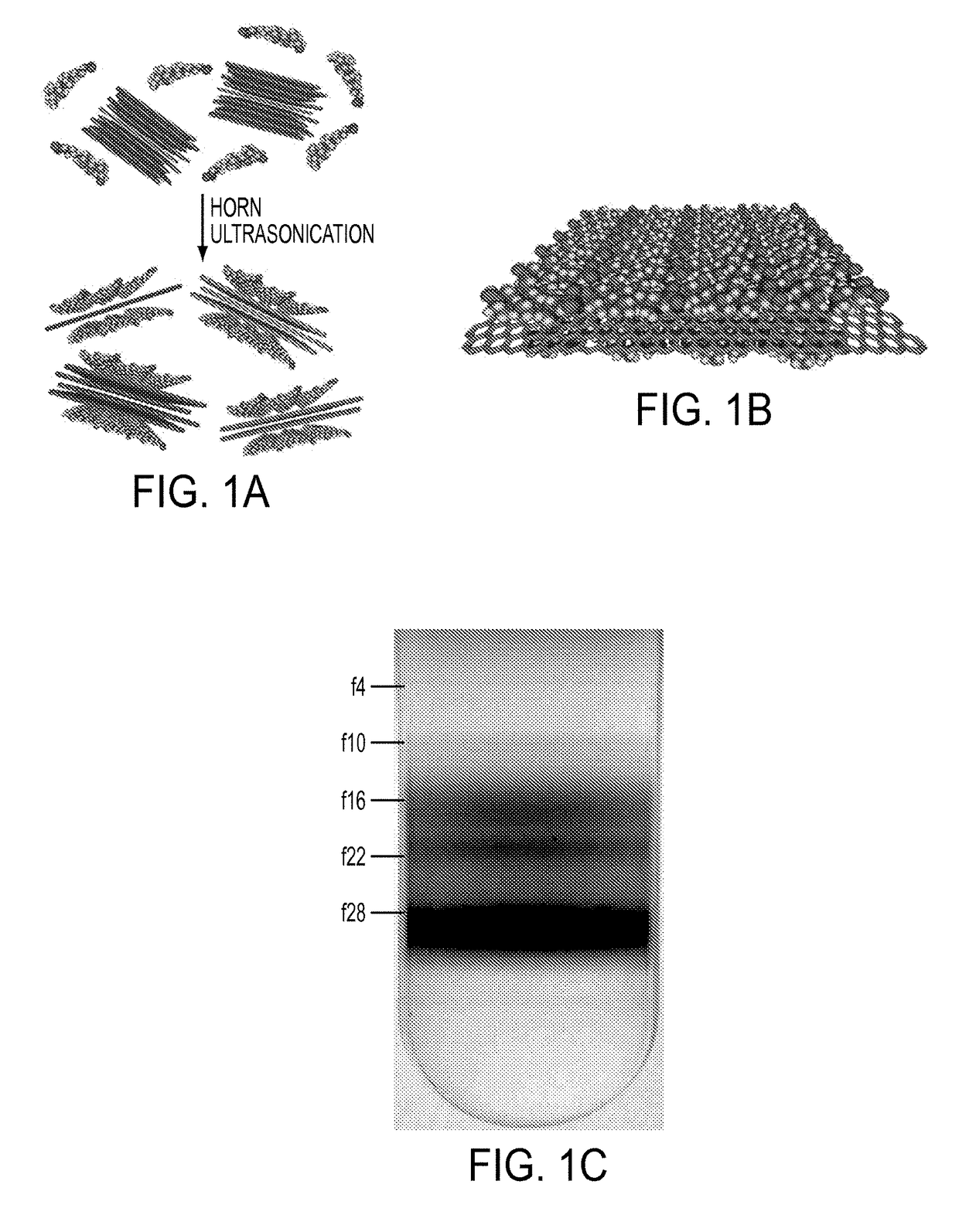
[0113]Graphene nanomaterial dispersions were prepared by horn ultrasonication of naturally occurring graphite flakes in an aqueous solution containing a surface active component. More specifically, six grams of natural graphite flakes (3061 grade material from Asbury Graphite Mills, Asbury, N.J., USA) were added to 70 mL of a 2% w / v sodium cholate (SC) aqueous solution inside a ˜120 mL stainless steel beaker. This mixture was chilled in an ice water bath and ultrasonicated using a Fisher Scientific Model 500 Sonic Dismembrator with a 13-mm-diameter tip for one hour at a power level of 51-52 W. Large initial loadings of graphite were chosen to maximize the concentrations of graphene exfoliated into the SC solution given the low cost of graphite flakes (˜$0.02 per gram). The sonicated graphene nanomaterial dispersions appeared as a gray-black slurry, suggesting the presence of both thin graphene nanosheets and thicker graphite flakes.

example 2

Sedimentation Centrifugation

[0114]Sedimentation centrifugation was performed to remove the fast sedimenting thick graphite materials from the sonicated graphene nanomaterial dispersions from Example 1. Specifically, the graphene nanomaterial dispersions were centrifuged in filled 2 mL eppendorf tubes using a tabletop centrifuge (Eppendorf Model 5424 Microcentrifuge) using four different conditions summarized in Table 1. The black supernatant resulting from the sedimentation centrifugation processing was believed to consist of predominantly few-layer graphene nanoflakes. The sedimented graphene nanomaterial dispersions were observed to be stable for several weeks at loadings in excess of 90 μg / mL. After centrifugation, the top 1 mL layer of the dispersion was decanted carefully from each eppendorf tube. Optical absorbance measurements were taken with a Cary 500 spectrophotometer (Varian) to estimate the concentration of graphene nanomaterials in the dispersions using an average absor...

example 3

Concentration of Graphene Dispersions by Ultracentrifugation in a Step Gradient

[0116]To obtain concentrated dispersions of graphene nanoflakes, the sedimented dispersions from Example 2 were centrifuged in a step density gradient. Specifically, the step gradients were prepared from a dense 6 mL underlayer containing about 60% w / v iodixanol (density of about 1.32 g mL−1) and about 2% w / v SC, followed by a graphene overlayer of ˜32 mL (density of about 1.0 g mL−1) added carefully on top, and ultracentrifuged in an SW 28 rotor (Beckman Coulter) for 24 hours at 28 krpm and a temperature of 22° C. Ultracentrifugation of the step gradients caused the graphene nanosheets to sediment rapidly to the point where the density of the medium changed discontinuously. In this region, the few-layer graphene nanoflakes with low buoyant densities halted their sedimentation as they reached their isopycnic points while the denser thick graphite flakes continued their motion until they eventually form a ...


PUM

PropertyMeasurementUnit
mean thicknessaaaaaaaaaa

Abstract

The present teachings provide, in part, methods of separating two-dimensional nanomaterials by atomic layer thickness. In certain embodiments, the present teachings provide methods of generating boron nitride nanomaterials having a controlled number of atomic layer(s).

Description

[0001]This application is a continuation in part of and claims priority to and the benefit of application Ser. No. 14 / 528,729 filed Oct. 30, 2014 and Issued as U.S. Pat. No. 9,221,064 on Dec. 29, 2015, which is a continuation in part of and claimed priority to and the benefit of application Ser. No. 14 / 507,240 filed Oct. 6, 2014 and Issued as U.S. Pat. No. 9,114,405 on Aug. 25, 2015, which is a divisional of and claimed priority to and the benefit of application Ser. No. 12 / 856,348 filed Aug. 13, 2010 and issued as U.S. Pat. No. 8,852,444 on Oct. 7, 2014 which claimed priority to and the benefit of provisional application Ser. No. 61 / 234,132, filed on Aug. 14, 2009—each of which is incorporated by reference herein in its entirety.[0002]This invention was made with government support under grant numbers DMR-0520513, EEC-0647560, DMR-0706067, DMR-1006391, DMR-1121262 and DMR-1505849 awarded by the National Science Foundation and grant numbers N00014-09-1-0180 and N00014-09-1-0795 awar...

Claims


Application Information

Patent Timeline
Patent Type & Authority Patents(United States)
IPC IPC(8): B01D21/26C01G39/00C01G41/00B82Y30/00B82Y40/00C01G39/06C04B35/52C04B35/583C01B21/064C01G29/00B03D3/00
CPCC01B32/196C01B32/194C01B21/064B01D21/26B03D3/00B82Y30/00B82Y40/00C01B21/0648C01G29/006C01G39/06C01G41/00C04B35/522C04B35/583C01B32/19C01B32/20C01B2204/02C01B2204/04C01B2204/06C01B2204/28C01P2004/20C01P2004/24C04B2235/386C04B2235/425C04B2235/5292C04B2235/5454Y10S977/845Y10T436/255Y10T436/25375
Inventor HERSAM, MARK C.GREEN, ALEXANDER A.ZHU, JIAN
Owner NORTHWESTERN UNIV
Why Eureka
Try Eureka