System, apparatus and method for producing a well

a wellbore and wellbore technology, applied in the direction of wellbore/well accessories, fluid removal, insulation, etc., can solve the problems of serious problems such as hydrate formation, gas hydrate formation, and undesirable formation of gas hydrates, so as to facilitate downward movement, facilitate upward movement, and reduce the viscosity of production fluids

Active Publication Date: 2018-03-06
CHEVROU USA INC
View PDF10 Cites 3 Cited by
  • Summary
  • Abstract
  • Description
  • Claims
  • Application Information

AI Technical Summary

Benefits of technology

[0009]A pump may be adapted for transmission of heat to the production fluids in the inner space, thereby elevating the temperature of the production fluids. The system may be configured for transferring heat carried by the production fluids to the lower end of the wellbore to reduce the formation of gas hydrates in the wellbore. In general, adding heat to the lower end of the wellbore assists in inhibiting undesirable gas hydrate formation.
[0013]In one embodiment of the invention, a system for producing oil and gas from a wellbore penetrating a subterranean formation includes (a) the wellbore lined with a casing, the wellbore having an upper end and a lower end, and the lower end of the wellbore being adjacent the subterranean formation. The wellbore is configured to receive production fluids and gas from a production zone of the subterranean formation. The casing is tubular in shape with an interior cavity. The system includes (b) production tubing positioned within the interior cavity of the casing and (c) a pump connected to the production tubing, the pump being adapted for lifting hydrocarbons within the production tubing. The system includes (d) an isolation sleeve positioned circumferentially outside of the production tubing and within the interior cavity of the casing, (e) an inner space between the isolation sleeve and the production tubing, and (f) an outer space between the isolation sleeve and the casing. (g) The isolation sleeve being configured to facilitate the upward movement, within the outer space, of the production fluids and gas towards the upper end of the wellbore. (h) The isolation sleeve being configured to facilitate the downward movement, within the inner space, of the production fluids toward the lower end of the wellbore. In the system, (i) the wellbore is being drilled to a depth having a subterranean formation temperature that is high enough to elevate a temperature of the production fluids to a predetermined temperature such that the temperature of the production fluids is elevated to the predetermined temperature by at least the depth of the wellbore. In the system, (j) the system is being configured for transferring heat carried by the production fluids to the upper end of the wellbore to reduce viscosity of the production fluids, increase production rate, reduce formation of gas hydrates, reduce formation of paraffins, or any combination thereof in the wellbore.
[0014]In one embodiment of the invention, a method of producing oil and gas from a wellbore is provided. The wellbore having a casing penetrating a subterranean formation, the wellbore having an upper end and a lower end, the wellbore configured to receive production fluids and gas from a production zone of the subterranean formation, and the wellbore being drilled to a depth having a subterranean formation temperature that is high enough to elevate a temperature of the production fluids to a predetermined temperature. The method includes (a) providing production tubing within an interior cavity of the casing, the production tubing being connected to a pump, the pump being adapted for lifting hydrocarbons within the production tubing; (b) providing an isolation sleeve positioned circumferentially outside of the production tubing and within the interior cavity the casing, there being an inner space between the isolation sleeve and the production tubing, further providing an outer space between the isolation sleeve and the casing; and (c) moving production fluids and gas within the outer space towards the upper end of the wellbore. The method further includes (d) separating the production fluids from the gas, (e) moving production fluids downward within the inner space adjacent the pump; (f) transferring heat from the depth of the wellbore to the production fluids; (g) elevating the temperature of the production fluids to the predetermined temperature by at least the depth of the wellbore; and (h) transferring heat carried by the production fluids towards the upper end of the wellbore to reduce viscosity of the production fluids, increase production rate, reduce formation of gas hydrates, reduce formation of paraffins, or any combination thereof in the wellbore Jj
[0015]In one embodiment of the invention, a system for isolating gas in a wellbore is provided. The wellbore having a casing with an interior cavity formed by an interior surface, the wellbore having an upper end and a lower end, the wellbore configured to receive production fluids and gas from a production zone of a subterranean formation, and the wellbore being drilled to a depth having a subterranean formation temperature that is high enough to elevate a temperature of the production fluids to a predetermined temperature. The system includes (a) a polished bore receptacle forming a seal with the interior surface of the casing; and (b) an annular seal locator sub mated with the polished bore receptacle, the annular seal locator sub being configured to form a collection space below the annular seal locator sub to collect gas within the casing of the wellbore, the annular seal locator sub further comprising at least one penetration adapted for a safety valve. In the system, (c) the wellbore being drilled to a depth having a subterranean formation temperature that is high enough to elevate a temperature of the production fluids to a predetermined temperature such that the temperature of the production fluids is elevated to the predetermined temperature by at least the depth of the wellbore. (d) The system being configured for transferring heat carried by the production fluids to the upper end of the wellbore to reduce viscosity of the production fluids, increase production rate, reduce formation of gas hydrates, reduce formation of paraffins, or any combination thereof in the wellbore.

Problems solved by technology

A problem in the production of oil and gas from subsea wellbores is the undesirable formation of gas hydrates.
Gas hydrates pose a problem for the oil and gas industry as more deepwater gas enters the supply stream.
Hydrate formation is a serious problem for producers moving gas from offshore wells to onshore processing facilities.
Clearing plugged lines is expensive and time-consuming, and may take as long as twenty days.
It has been estimated that controlling and preventing gas hydrate formation costs the industry hundreds of millions of dollars annually.
ESP systems may be subject to undesirable cavitation if excess gas is present in the flow stream being pumped.
Shock waves caused by cavitation in pumps may damage moving parts within the pump.

Method used


Image

  • System, apparatus and method for producing a well
  • System, apparatus and method for producing a well

Examples


Embodiment Construction

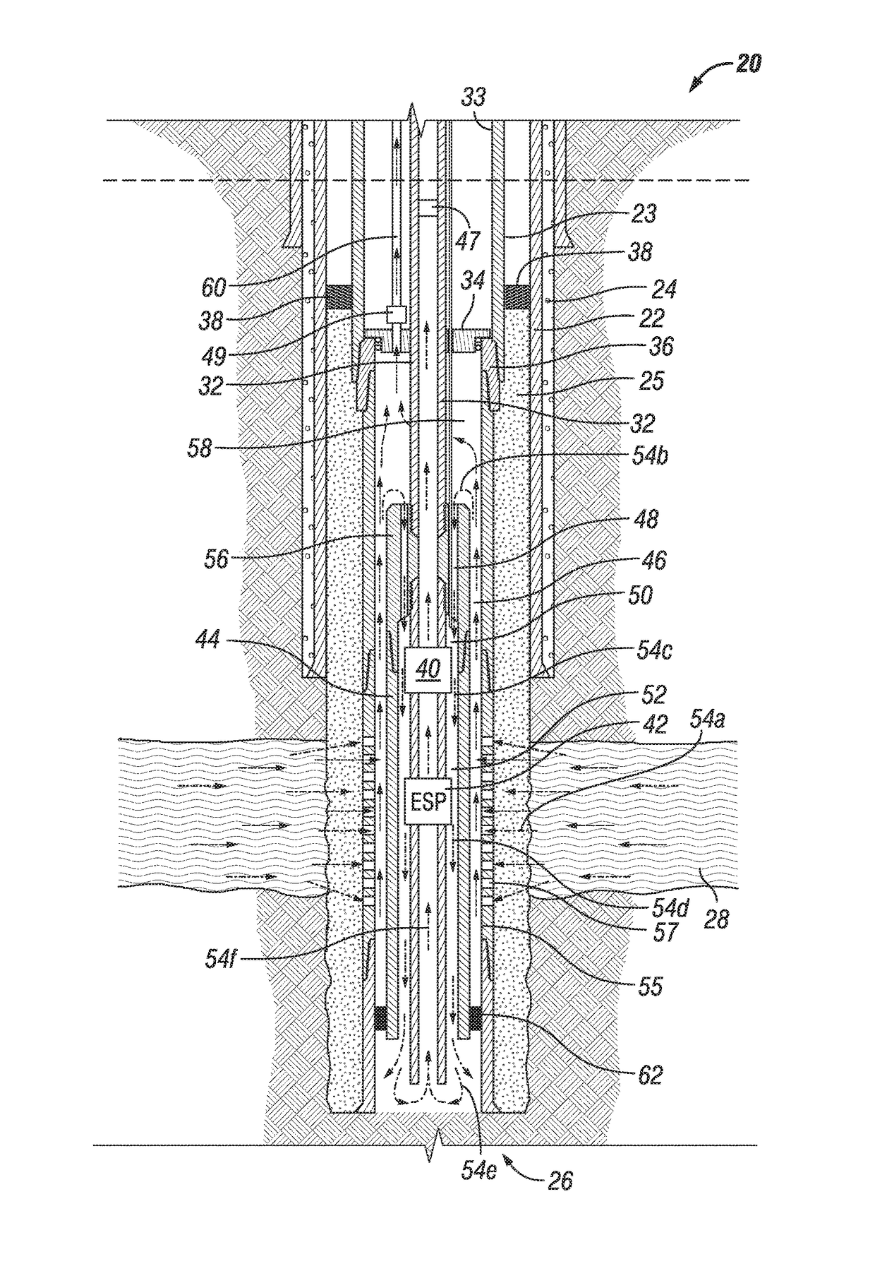
[0017]A system, apparatus and method is provided that is capable of providing heat across a produced interval during oil and gas production that may serve to minimize or reduce undesirable formation of gas hydrates in the wellbore. In one embodiment the configuration provides a means to recycle and conserve heat generated by an electrical submersible pump (“ESP”). Also, it may be possible in some applications to provide additional heat downhole by the use of one or more heating elements to apply heat to produced fluids that are circulated downhole, thereby minimizing the undesirable formation of gas hydrates within or adjacent to the wellbore interface. An isolation sleeve may be employed that extends across the completion interval and is sealed near the bottom in a seal receptacle, causing the flow stream from the wellbore to flow up the outside of the isolation sleeve. The fluids and gas may be separated, as further described herein. Also, such heat could assist in producing heavy...


PUM


Abstract

A system is provided that is capable of providing heat across a produced interval during oil and gas production to minimize or reduce undesirable formation of gas hydrates in the wellbore. In one embodiment, the configuration provides a means to recycle heat generated by an electrical submersible pump. Heat from the pump may be applied downhole. One configuration is capable of providing for downhole separation of gas from produced fluids to reduce or eliminate gas transit through the pump. A heating element also may apply heat to produced fluids. An orifice may apply heat to produced fluids. The wellbore being drilled to a depth having a subterranean formation temperature that is high enough to elevate a temperature of the production fluids to a predetermined temperature such that the temperature of the production fluids is elevated to the predetermined temperature by at least the depth of the wellbore.

Description

CROSS REFERENCE TO RELATED INVENTIONS[0001]This application claims priority as a continuation-in-part application from U.S. application Ser. No. 13 / 585,483, filed on Aug. 14, 2012, which claims priority from U.S. Provisional Patent Application No. 61 / 524,596, filed on Aug. 17, 2011, the disclosures of both of which are also hereby incorporated by reference in their entireties.FIELD OF THE INVENTION[0002]The invention is directed to a system, apparatus and method for producing fluids and gas from a wellbore.BACKGROUND OF THE INVENTION[0003]A problem in the production of oil and gas from subsea wellbores is the undesirable formation of gas hydrates. A gas hydrate is a crystalline solid consisting of molecules of gas, usually methane, surrounded by a “cage” of water molecules. Gas hydrates have the visual appearance of ice. Methane hydrate is stable in ocean floor sediments at water depths of greater than about 300 meters. Certain temperature and pressure conditions encourage the forma...

Claims


Application Information

Patent Timeline
Patent Type & Authority Patents(United States)
IPC IPC(8): E21B43/24E21B36/00E21B43/38E21B43/12
CPCE21B43/24E21B36/00E21B43/38E21B43/121E21B43/128E21B36/005
Inventor ARMISTEAD, GEORGE T.
Owner CHEVROU USA INC
Why Eureka
Try Eureka