
Manufacturing facility for quicklime, and manufacturing facility and manufacturing process for slaked lime

a manufacturing facility and quicklime technology, applied in the field of quicklime manufacturing facilities and manufacturing processes, can solve the problems of difficult recovery, high cost for separating and recovering cosub>2 /sub>gas, and difficulty in recovering, so as to suppress the occurrence of coating trouble and the like, high active powdery quicklime, and small specific surface area

Inactive Publication Date: 2018-03-13
MITSUBISHI MATERIALS CORP
View PDF22 Cites 0 Cited by
  • Summary
  • Abstract
  • Description
  • Claims
  • Application Information

AI Technical Summary

Benefits of technology

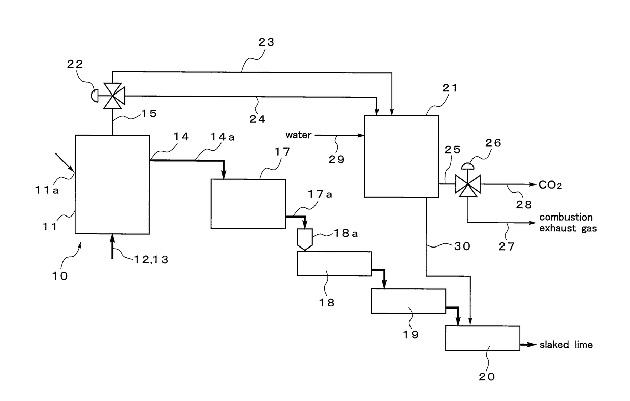
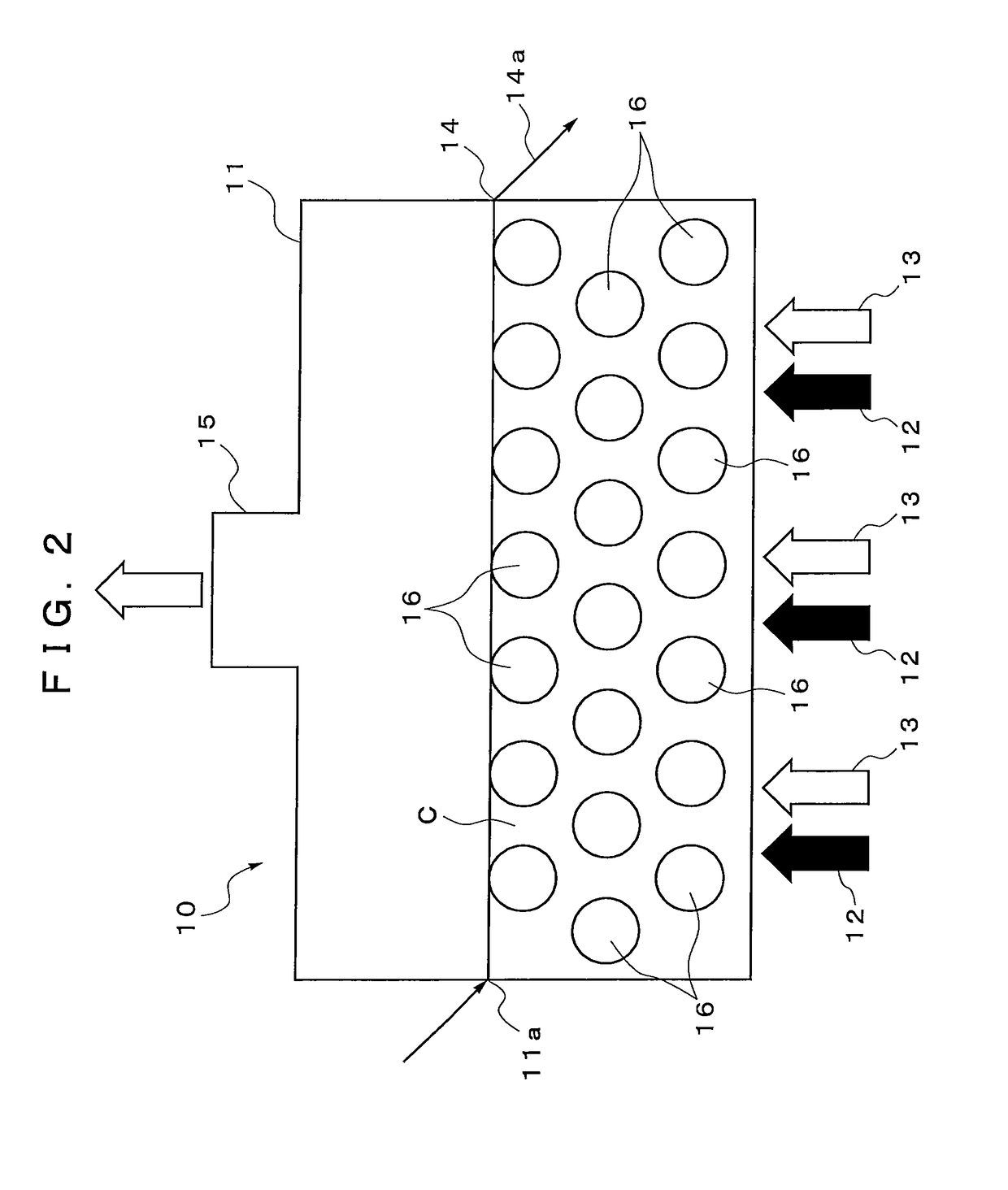
[0025]According to the first aspect or the second aspect, the limestone is supplied from the supply port, while the heat medium filled in the regenerative calciner is heated by the heating means to a temperature not less than the calcination temperature of limestone so that the temperature of the atmosphere in the regenerative calciner is maintained at a temperature not less than the calcination temperature. Then, the particles of the limestone are effectively heated and calcined by entering between the particles of the heat medium having a particle diameter larger than the particle diameter of the limestone. Thereby, the chemical reaction as represented by the formula: CaCO3→CaO+CO2↑ is caused so that quicklime is produced and CO2 gas is generated. As a result, the inside of the regenerative calciner is filled with the CO2 gas generated by the calcination of limestone, and the concentration of CO2 gas in the regenerative calciner becomes about 100%. Thereby, the CO2 gas having a concentration of about 100% can be recovered from the regenerative calciner via the exhaust pipe. In addition, when the calcination temperature is set to a relatively low temperature, it is possible to obtain highly active powdery quicklime.
[0026]At this time, in the regenerative calciner described above, limestone is heated and calcined by the heat medium which has a particle diameter larger than the particle diameter of the limestone and hence which has an extremely small specific surface area. Thereby, a large amount of heat can be stored in the regenerative calciner. Also, even when the heat medium is heated to a temperature not less than the calcination temperature of the limestone, that is, to a temperature not less than 1000° C. in the regenerative calciner, sticking and fusion between the particles of the heat medium or sticking and fusion between the particle of the heat medium and the furnace wall are suppressed, so that the occurrence of a coating trouble and the like can be suppressed.
[0027]Further, since the heat medium having a particle diameter larger than the particle diameter of the limestone is used, the produced powdery quicklime can be simply taken out from the regenerative calciner by being fluidized by the CO2 gas generated at the time of calcination described above and then by being made to overflow from the regenerative calciner, or by being discharged from the regenerative calciner together with the CO2 gas generated at the time of calcination and then by being separated from the CO2 gas by solid-gas separation.
[0028]Here, as the heat medium, it is possible to use ceramics materials, such as silica (SiO2) and alumina (Al2O3), and metal materials, such as a heat-resistant alloy, as long as the materials have heat resistance to the heating temperature in the regenerative calciner, and have abrasion resistance at the time of being mixed with limestone.
[0029]Particularly, as in the second aspect, when quicklime is used as the heat medium, there is an advantage that the melting point of the heat medium is as high as about 2500° C. and that the particles of the heat medium are hardly fused to each other. It is also preferred to use quicklime as the heat medium, because no adverse effect is caused even in the case where, while the calcination of the limestone is repeated in the regenerative calciner by using quicklime as the heat medium, fine powder is generated as a result of gradual abrasion of the quicklime.
[0030]Further, according to one of the third aspect to the fifth aspect, highly active powdery quicklime obtained by one of the first aspect and the second aspect can be used as a raw material, and hence slaked lime having high reactivity can be manufactured.

Problems solved by technology

Therefore, in spite of the fact that the discharge amount of CO2 is large, there is a problem that the CO2 gas has a concentration of about 30 to 35% and hence is difficult to be recovered.
However, the methods have a problem that the cost for recovering CO2 gas is still very high.
However, in this method, the cost for separating and recovering CO2 is high, and hence this method is not realized for the same reason as that for the above described methods.

Method used


Image

  • Manufacturing facility for quicklime, and manufacturing facility and manufacturing process for slaked lime
  • Manufacturing facility for quicklime, and manufacturing facility and manufacturing process for slaked lime
  • Manufacturing facility for quicklime, and manufacturing facility and manufacturing process for slaked lime

Examples


Embodiment Construction

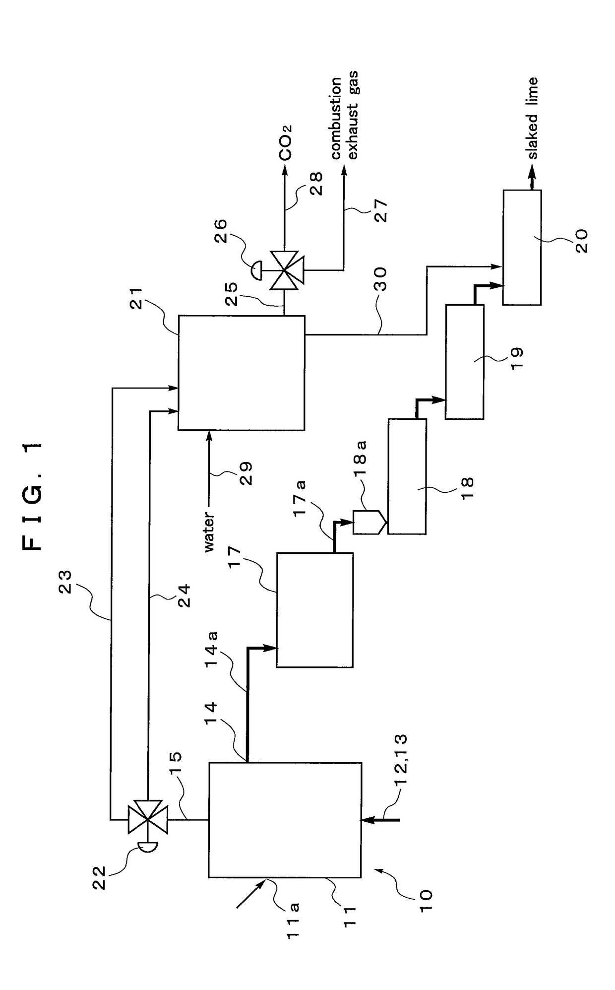
[0039]FIG. 1 and FIG. 2 show an embodiment of a manufacturing facility for quicklime according to the present invention, and an embodiment of a manufacturing facility for slaked lime using the manufacturing facility for quicklime. Reference numeral 10 in FIG. 1 and FIG. 2 denotes a manufacturing facility for quicklime, and reference numeral 11 denotes a regenerative calciner which is a main portion of the manufacturing facility for quicklime.

[0040]The regenerative calciner 11 is a horizontal furnace configured such that a supply port 11a for supplying, to the inside of the furnace, limestone C crushed into particles having a particle diameter of 10 μm to 1 mm is provided at an upper part of the regenerative calciner 11, and such that a burner (heating means: not shown) capable of maintaining the temperature of the atmosphere in the regenerative calciner 11 at a temperature not less than the calcination temperature of the limestone (for example, about 900° C.) is provided at a lower ...


PUM

PropertyMeasurementUnit
diameteraaaaaaaaaa
temperatureaaaaaaaaaa

Abstract

A manufacturing facility for quicklime is provided, which can manufacture highly active quicklime by a simple manufacturing facility, and which can also separate and recover, in a high concentration, CO2 gas generated at the time of manufacturing quicklime. The manufacturing facility for quicklime is configured by including: a regenerative calciner 11 which has a supply port 11a for supplying granular limestone C into the regenerative calciner 11, heating means capable of maintaining the temperature of the atmosphere in the regenerative calciner 11 at a temperature not less than the calcination temperature of the limestone, an exhaust pipe 15 connected to an upper part of the regenerative calciner 11 so as to discharge combustion exhaust gas of the heating means and CO2 gas generated by the calcination of limestone, and a discharge port 14 for taking out quicklime produced by the calcination; and a heat medium 16 which has a particle diameter larger than the particle diameter of the limestone and which is filled in the regenerative calciner 11.

Description

TECHNICAL FIELD[0001]The present invention relates to a manufacturing facility for quicklime, and a manufacturing facility and manufacturing process for slaked lime, which can manufacture highly reactive slaked lime and which can separate and recover, in a high concentration, CO2 gas generated at the time of calcining quicklime as a raw material of the slaked lime.BACKGROUND ART[0002]In recent years, attempts for reducing carbon dioxide (CO2) gas, which is a main cause of the global warming phenomenon, have been made worldwide and in all industries.[0003]The lime industry, together with the cement industry, the electric power industry, the steel industry, and the like, is one of the industries which discharge a large amount of CO2 gas. For this reason, the reduction in the amount of CO2 gas discharged in the lime industry greatly contributes to the reduction in the total amount of CO2 gas discharged in Japan.[0004]FIG. 5 shows a common quicklime manufacturing facility in the lime in...

Claims


Application Information

Patent Timeline
Patent Type & Authority Patents(United States)
IPC IPC(8): C04B2/04C04B2/08C04B2/10C04B2/12
CPCC04B2/08C04B2/04C04B2/106C04B2/12C04B2/10Y02P40/42C01F11/06C01F11/16C04B2/00C04B2/02Y02P40/40
Inventor HIGUCHI, NAOHIROSHIMA, HIROKAZU
Owner MITSUBISHI MATERIALS CORP
Learn More