Methods of separation of pyrolysis oils

a technology of pyrolysis oil and separation method, which is applied in the direction of hydrocarbon oil treatment products, thermal non-catalytic cracking, coke ovens, etc., can solve the problems of complex mixture of compounds, distillate instability, and failure to yield commercially valuable fractions, and achieve the effect of effective fuel oil products

Active Publication Date: 2018-03-20
RJ LEE GRP INC
View PDF11 Cites 18 Cited by
  • Summary
  • Abstract
  • Description
  • Claims
  • Application Information

AI Technical Summary

Benefits of technology

[0013]The present invention has provided a solution to the shortcomings of the hereinbefore discussed prior art by providing effective methods for a processing pyrolysis vapor to effect separation of commercially desired fractions from heavier fractions suitable for use as fuel oil. More specifically, in a preferred embodiment, a first phase separation of the pyrolysis gas results in a lighter fraction and a heavier fraction. This is followed by a second phase subjecting the lighter fraction to plate distillation to separate the commercially desirable products. The heavier fraction in a third phase is subjected to oxidative desulfurization with nitrogen containing organic compounds being removed with the desufurization process are employed to produce an effective fuel oil product. A preferred initial separation of the pyrolysis oil involves thin film distillation as this effectively and economically produces the desired first stage of separation. Certain preferred parameters with respect to the plate distillation process as preferred features are disclosed.

Problems solved by technology

Attempts to isolate fractions containing these compounds in a commercially viable fraction have not been successful.
However, attempts to isolate fractions containing these compounds have not yielded commercially valuable fractions.
This is due to many issues from the complex nature of tire-derived pyrolysis oil.
Attempts at direct distillation of the pyrolysis oils yield complex mixtures of compounds and distillate instability during distillation.
(Production of dl-limonene by vacuum pyrolysis of used tires, Journal of Analytical and Applied Pyrolysis 57 pp, 91-107, 2001.) found that pyrolytic breakdown products of limonene plus thiophene and other sulfur compounds co-eluted with limonene and made clean separation of limonene difficult.
This again, shows the difficulty in isolating limonene from pyrolysis oil.

Method used


Image

  • Methods of separation of pyrolysis oils
  • Methods of separation of pyrolysis oils
  • Methods of separation of pyrolysis oils

Examples


example

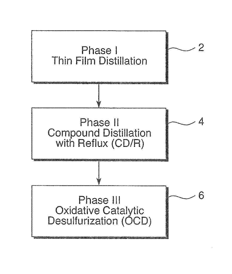
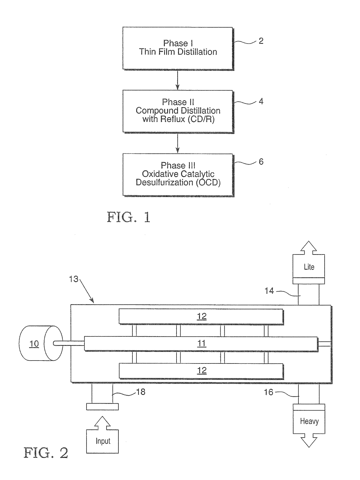
[0038]An example of Phase II will be considered. The feed material is the lighter fraction emerging from the Phase I thin film distillation.

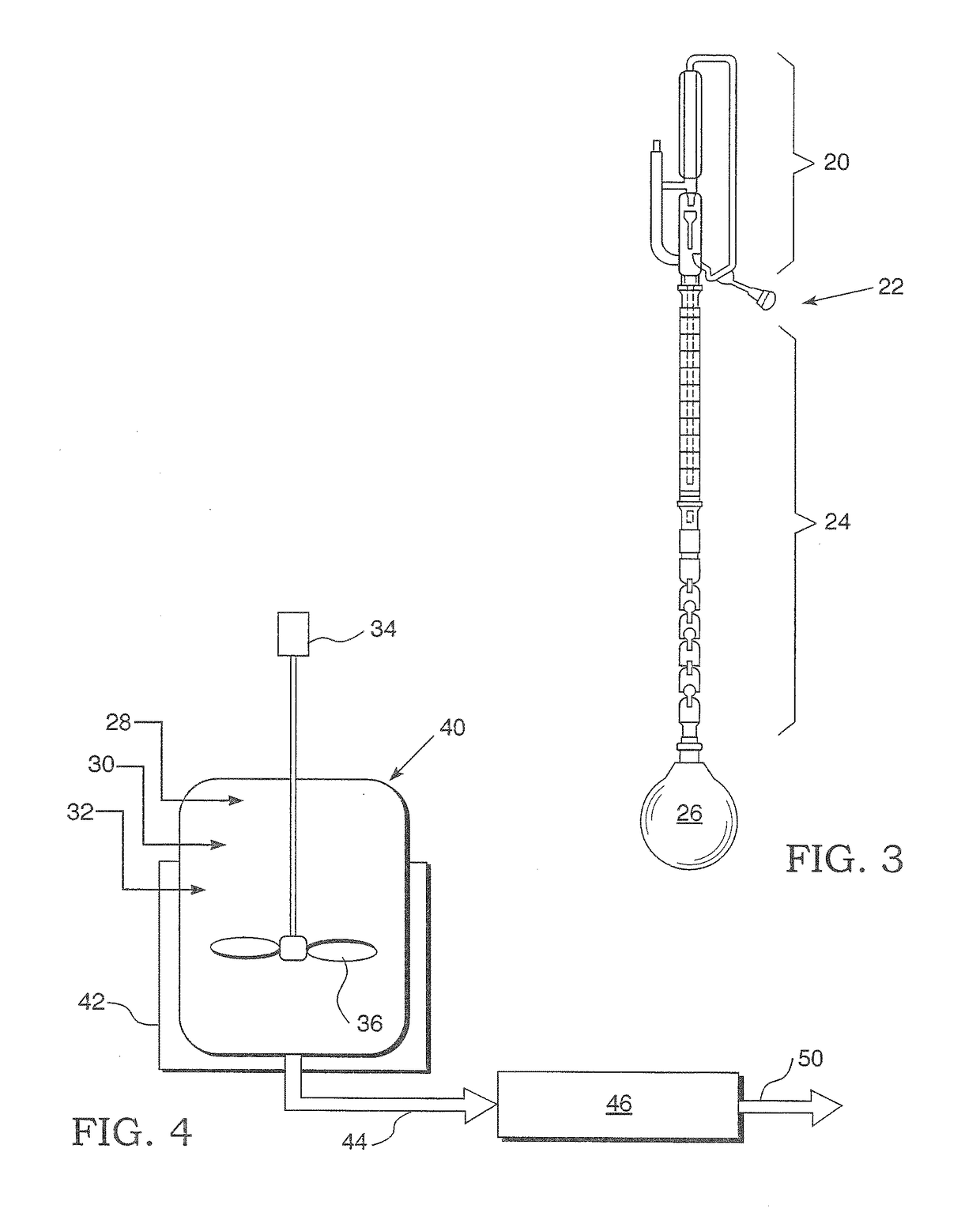
[0039]The system is set initially to a range of 100-400 torr with a preferred setting of about 300 torr vacuum for collection of lower fraction which is collected from approximately 20° C. to 25° C. until the distillate reaches about 134° C. and 145° C., more preferred between 139° C. and 141° C. This lower fraction can be split into several temperature cuts. An example is as shown in TABLE 1.

[0040]

TABLE 1Temp / PreferredvacuumpressureTemp (° C.)Temp (° C.)(torr)cut 1Start-115° C.start-105.8300cut 2106° C.-138° C.300cut 3139° C.-141° C.300

[0041]The described cuts consist on several low boiling point highly volatile solvent chemicals. These include, but are not limited to, Xylene, Toluene, and Styrene making the individual, as well as the combined solution(s), extremely valuable in the industrial market.

[0042]After collection of fractions up to 141...


PUM

PropertyMeasurementUnit
temperatureaaaaaaaaaa
weight percentaaaaaaaaaa

Abstract

Methods for processing pyrolysis oil employs two or more of the following steps: A first separation creates (a) a lighter fraction and heavier fraction, (b) subjecting the lighter fraction to distillation and (c) subjecting the heavy fraction to removal of at least one of sulfur and nitrogen.

Description

BACKGROUND OF THE INVENTION1. Field of the Invention[0001]The present invention relates to methods of extracting an enhanced feedstock for distillation from pyrolysis oil and, more specifically, it relates to methods for performing an initial separation which establishes a lighter fraction and a heavier fraction. The lighter fraction is subjected to plate distillation and the heavier fraction is subjected to the removal of sulfur and nitrogen compounds therefrom to facilitate the use of the heavier fraction as heavy fuel oil. A preferred starting material is obtained from vehicular tires.2. Description of the Prior Art[0002]It has been known to subject rubber, such as scrap tires, to pyrolysis with the process producing a solid fraction such as carbon black, a liquid hydrocarbon and a gas. The liquid hydrocarbon may have potential as a fuel oil. See U.S. Pat. Nos. 6,833,485; 6,835,861; and 7,341,646.[0003]U.S. Pat. No. 6,673,236 discloses the reduction of sulfur in petroleum middle ...

Claims


Application Information

Patent Timeline
Patent Type & Authority Patents(United States)
IPC IPC(8): C10G53/14
CPCC10G53/14C10G2400/30C10G7/06C10G2300/202C10G55/00C10G11/04C10G9/04C10G1/10C10G2300/1037C10B53/07
Inventor WISTROM, JONATHAN LYLEBEAVER, EARL RICHARDWISTROM, SKYLER LINNLEVINE, ALAN M.LEE, RICHARD J.
Owner RJ LEE GRP INC
Why Eureka
Try Eureka