
Method and device for the non-destructive inspection of a rotationally symmetric workpiece having sections with difference diameters

a technology of rotationally symmetric workpieces and inspection devices, which is applied in the direction of instruments, material magnetic variables, and processing detected response signals, can solve the problems of difficult inspection tasks, the most frequent wear phenomenon observed in the shafts of wheel sets of rail vehicles, and the danger of geometric echoes “masking” relevant signals, etc., to achieve the effect of significantly improving the signal-to-noise ratio

Active Publication Date: 2018-03-20
GE SENSING & INSPECTION TECH GMBH
View PDF15 Cites 2 Cited by
  • Summary
  • Abstract
  • Description
  • Claims
  • Application Information

AI Technical Summary

Benefits of technology

The invention relates to a method and device for inspecting a workpiece using ultrasonic waves. The method involves amplifying the ultrasonic echo signals using a time-dependent or insonification angle-dependent amplification to compensate for sound-attenuating effects due to the geometric expansion of the sound field and insonification angles, improving the interpretation of flaws in the workpiece. The testing device also includes a probe with two ultrasonic transducers that have different travel directions, which enhances the sensitivity and accuracy of flaw detection. The device is compact and easy to use.

Problems solved by technology

The non-destructive inspection of rotationally symmetric workpieces having sections with different diameters by means of non-destructive inspection techniques often suffers from the problem of the geometrical structure of the workpiece causing geometry-related signals of the inspection technique used.
There is therefore the possibility of the intensive geometry echoes obscuring less intensive underlying signals that could be correlated with, for example, flaws to be detected in the workpiece.
Due to the limited dynamics of the signal processing used within the context of the inspection technique, there is therefore a danger of geometric echoes “masking” relevant signals, e.g. flaw signals.
It is obvious that the shafts of wheel sets of rail vehicles constitute safety-relevant components that are subject to natural wear over the long life span of rail vehicles.
In practice, the most frequent wear phenomenon observed in shafts of wheel sets of rail vehicles is the occurrence of incipient cracks, i.e. crack-like fatigue failures that start at the surface of the respective shaft.
Until this day, the inspection by means of ultrasound of rotationally symmetric workpieces having diameters that change from section to section, in particular of solid shafts of rail vehicles, constitutes a particularly challenging inspection task.
Moreover, the inspection of a wheel set of a rail vehicle often entails a downtime of the rail vehicle, which is directly connected to high downtime costs due to the rail vehicle being out of service.
If they are mounted, then an insonification from the shaft or from the end face (e.g. by means of a conical probe) is not possible with the ultrasound-based inspection methods known from the prior art.
Finally, the generation of an easily interpreted representation of the results of, for example, an ultrasound inspection obtained on a rotationally symmetric workpiece constitutes a problem which, as far as the applicant is aware, has so far been solved only to an insufficient extent.

Method used


Image

  • Method and device for the non-destructive inspection of a rotationally symmetric workpiece having sections with difference diameters
  • Method and device for the non-destructive inspection of a rotationally symmetric workpiece having sections with difference diameters
  • Method and device for the non-destructive inspection of a rotationally symmetric workpiece having sections with difference diameters

Examples


Embodiment Construction

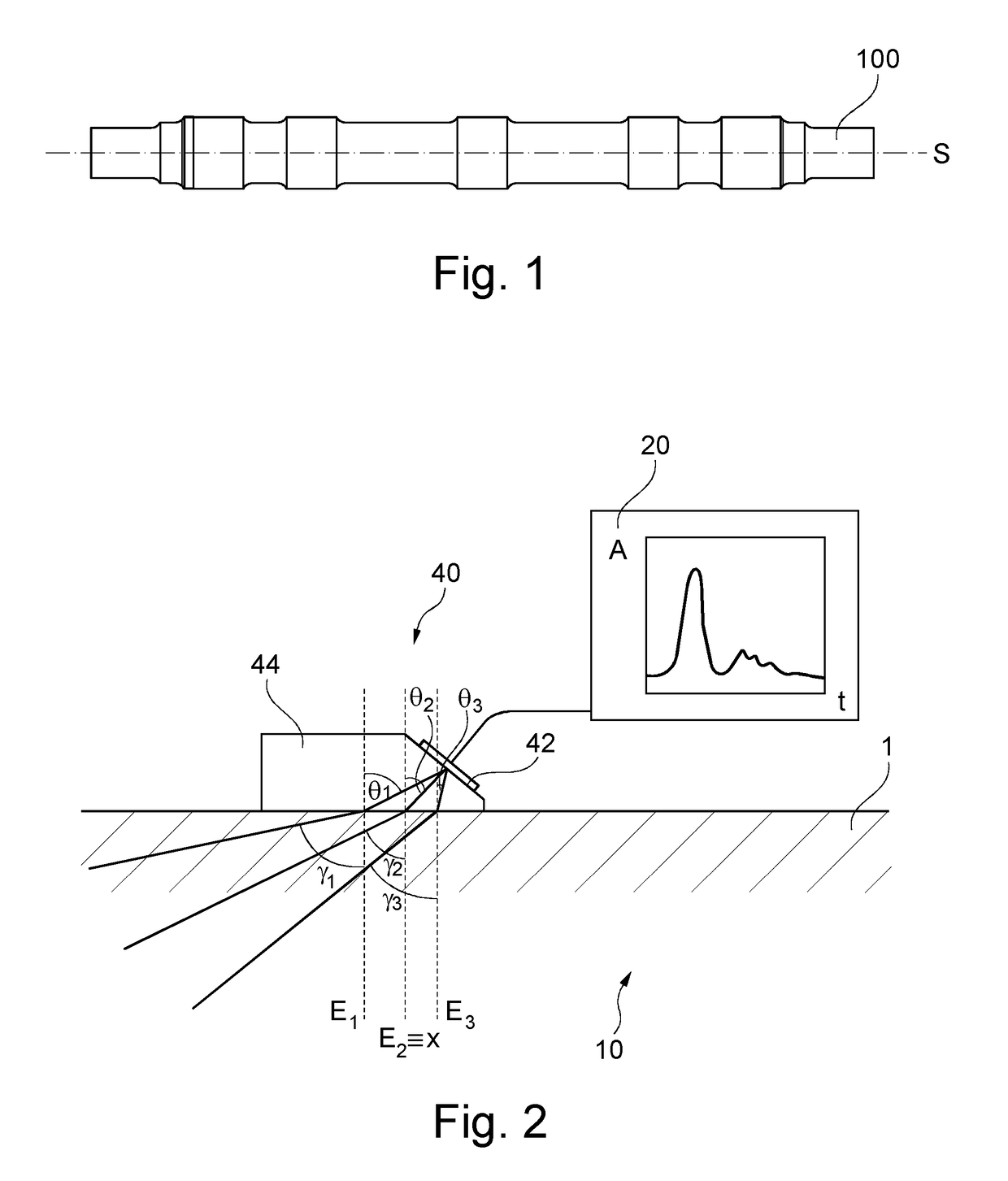
[0068]FIG. 1 shows a side view of a typical solid shaft 1 of a wheel set of a rail vehicle. It is a rotationally symmetric forging with a diameter changing from section to section, as becomes clear from FIG. 1. In particular, the shaft 1 comprises different sections with a constant diameter, which are provided for accommodating the wheel hubs, the rolling bearings, with which the solid shaft is rotatably mounted on the rail vehicle, and a centrally disposed brake disk. As a forging, a solid shaft according to FIG. 1 typically has a certain anisotropy of the sound velocity for ultrasound, which is produced by local structural changes caused by the forging process. In this case, the solid shaft 1 is rotationally symmetric to the drawn-in axis of rotation S.

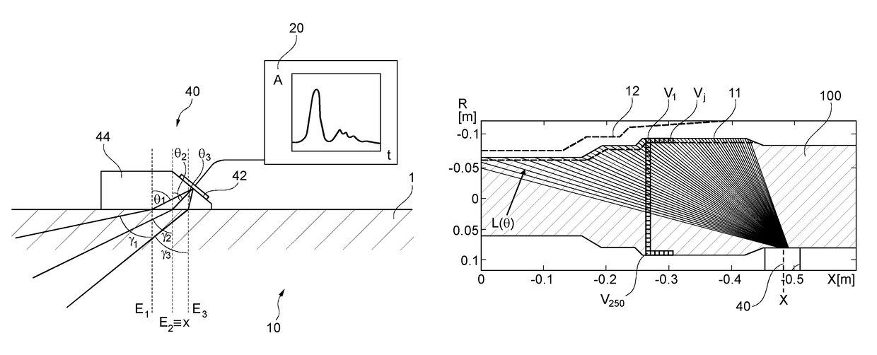
[0069]FIG. 2 shows a first exemplary embodiment of a testing device 10, which comprises a control unit 20 and a test probe 40 connected to it. The test probe 40 comprises a segmented ultrasonic transducer 42 of the phased array type...


PUM

PropertyMeasurementUnit
azimuth anglesaaaaaaaaaa
insonification angle Thetaaaaaaaaaaa

Abstract

A method and a device for the non-destructive inspection of a rotationally symmetric workpiece having sections with different diameters by a non-destructive inspection technique, such as ultrasound, are provided. Within the context of the method, a test data set characterizing the material properties of the workpiece is generated by the inspection technique. An azimuth angle-dependent indicated value set is generated therefrom. Subsequently, a representation of the workpiece is generated, wherein the elements of the indicated value set are depicted in the representation in a spatially resolved manner. In particular, a graphic representation of the surface of the workpiece can be generated in which flaw signals are displayed that may have been found.

Description

BACKGROUND[0001]The subject matter of the present invention is a method and a device for the non-destructive inspection of a rotationally symmetric workpiece having sections with different diameters by means of a non-destructive inspection technique, such as ultrasound, eddy currents or X-rays. An ultrasonic inspection in accordance with the pulse echo method is used with particular preference as the inspection technique. In a particularly development, the method and the device are suited, in particular, for the inspection of a workpiece with an anisotropic sound velocity. For example, an anisotropic sound velocity is frequently observed, for example, in forged solid shafts which can be used, for instance, in rail vehicles.[0002]The non-destructive inspection of rotationally symmetric workpieces having sections with different diameters by means of non-destructive inspection techniques often suffers from the problem of the geometrical structure of the workpiece causing geometry-relat...

Claims


Application Information

Patent Timeline
Patent Type & Authority Patents(United States)
IPC IPC(8): G01N29/00G01N29/22G01N29/38G01N29/44G01N29/06G01N23/18G01N29/04G01N27/90
CPCG01N29/00G01N23/18G01N29/043G01N29/069G01N29/38G01N29/44G01N29/221G01N2291/0289G01N27/9046
Inventor LINGENBERG, DIETER
Owner GE SENSING & INSPECTION TECH GMBH
Learn More