Junction field effect transistor (JFET) with first and second top layer of opposite conductivity type for high driving current and low pinch-off voltage

a junction field effect transistor and conductivity type technology, applied can solve the problems of not being completely satisfactory in all respects, still some problems to be overcome in the field of semiconductor devices and technology jfets, and achieve the effects of increasing driving current, reducing device pinch-off voltage, and high driving curren

Active Publication Date: 2018-03-27
VANGUARD INTERNATIONAL SEMICONDUCTOR CORPORATION
View PDF7 Cites 2 Cited by
  • Summary
  • Abstract
  • Description
  • Claims
  • Application Information

AI Technical Summary

Benefits of technology

[0005]Generally, forming a semiconductor device that has both a high driving current and a low pinch-off voltage (which is ideal for switching applications) is the primary criteria in the development of semiconductor devices. In order to achieve the aforementioned criteria, an n-type top layer and a p-type top layer are implanted between the source and the drain in the semiconductor substrate. More specifically, a portion of the two top layers with opposite conductivity types is formed under the gate of the semiconductor device which can increase the driving current and decrease the pinch-off voltage of the device without forming a well region under the gate. Moreover, compared to the traditional manufacturing process, the embodiments of the present disclosure can form a semiconductor device with a high driving current and a low pinch-off voltage without using additional masks for forming additional circuits for the device in the overall process.

Problems solved by technology

Although existing JFETs of semiconductor devices and methods for forming the same have been adequate for their intended purposes, they have not been entirely satisfactory in all respects.
Therefore, there are still some problems to be overcome in regards to the JFETs of semiconductor devices and technology.

Method used


Image

  • Junction field effect transistor (JFET) with first and second top layer of opposite conductivity type for high driving current and low pinch-off voltage
  • Junction field effect transistor (JFET) with first and second top layer of opposite conductivity type for high driving current and low pinch-off voltage
  • Junction field effect transistor (JFET) with first and second top layer of opposite conductivity type for high driving current and low pinch-off voltage

Examples


Embodiment Construction

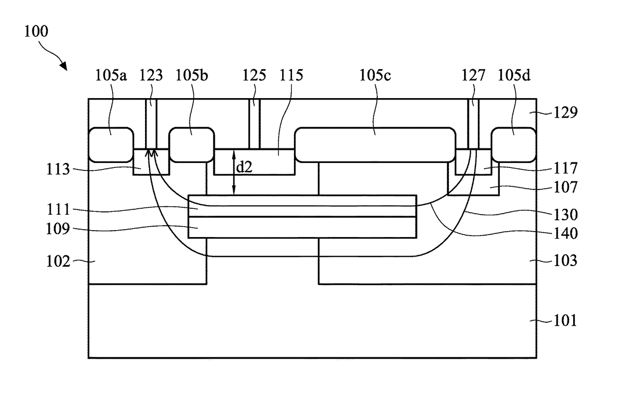
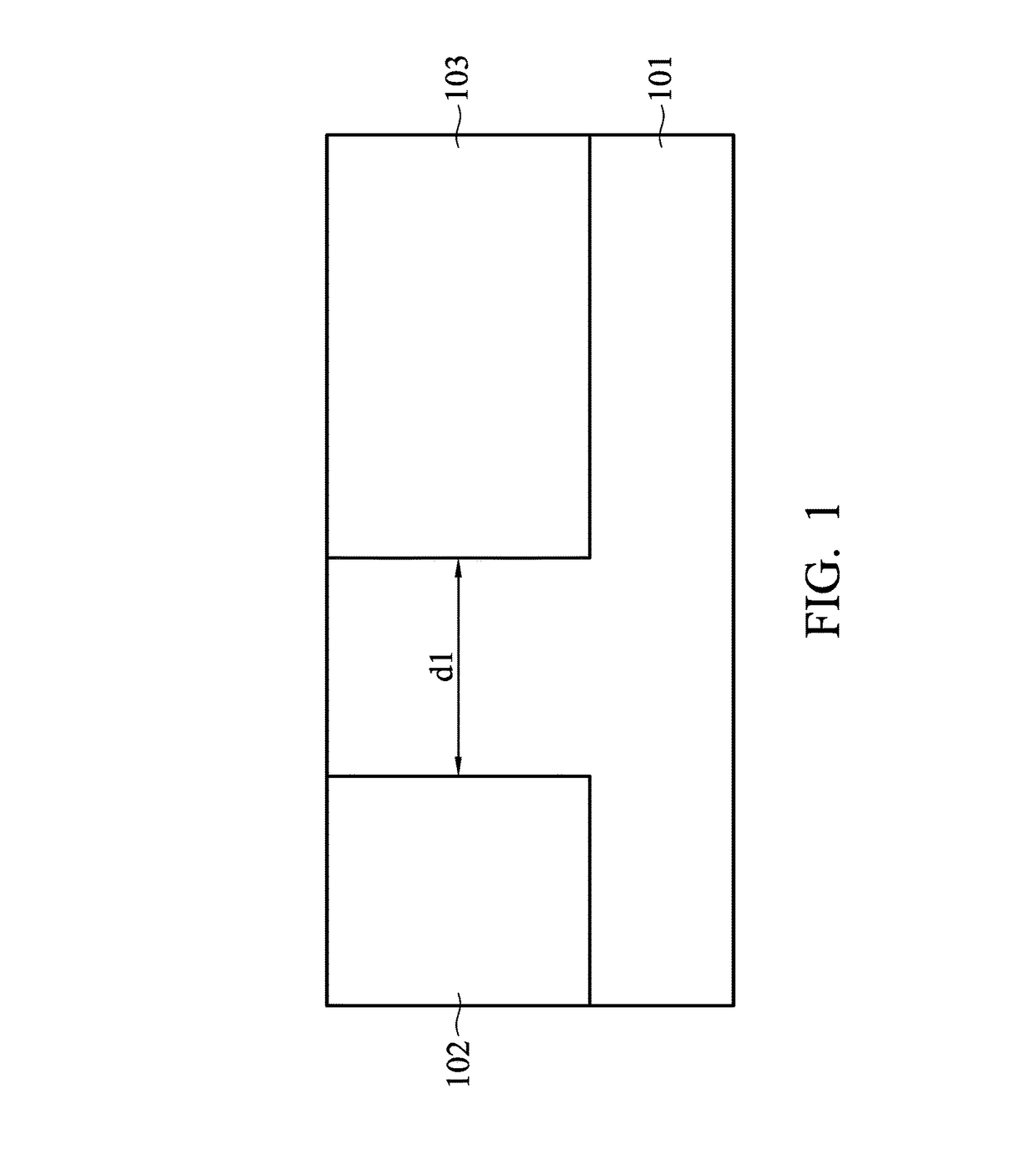
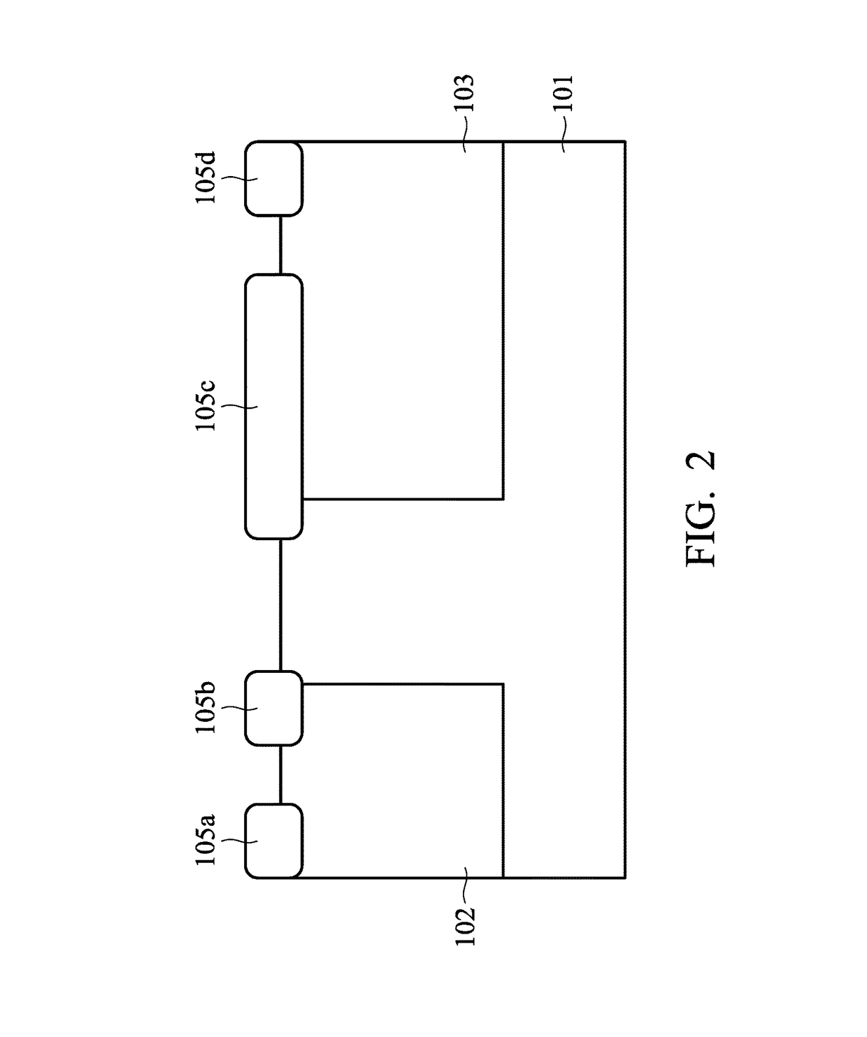
[0013]The following disclosure provides many different embodiments, or examples, for implementing different features of the subject matter provided. Specific examples of components and arrangements are described below to simplify the present disclosure. These are, of course, merely examples and are not intended to be limiting. For example, the formation of a first feature over or on a second feature in the description that follows may include embodiments in which the first and second features are formed in direct contact, and may also include embodiments in which additional features may be formed between the first and second features, such that the first and second features may not be in direct contact. In addition, the present disclosure may repeat reference numerals and / or letters in the various embodiments. This repetition is for the purpose of simplicity and clarity and does not in itself dictate a relationship between the various embodiments and / or configurations discussed.

[001...


PUM


Abstract

A semiconductor device includes a semiconductor substrate, a first well region, and a second well region. The semiconductor substrate has a first conductivity type. The first and second well regions are disposed in the semiconductor substrate. The first and second well regions have a second conductivity type that is opposite to the first conductivity type. The semiconductor device also includes a first top layer and a second top layer. The first top layer is disposed in the semiconductor substrate. The first top layer extends from the first well region to the second well region. The first top layer has the first conductivity type. The second top layer is disposed in the semiconductor substrate and on the first top layer. The second top layer extends from the first well region to the second well region. The second top layer has the second conductivity type.

Description

BACKGROUND OF THE INVENTIONField of the Invention[0001]The invention relates to semiconductor devices, and in particular to semiconductor devices having two top layers with opposite conductivity types and methods for forming the same.Description of the Related Art[0002]In the semiconductor industry, there are two major classes of field effect transistors (FETs); namely the insulated gate field effect transistor (IGFET), which is more commonly known as a metal oxide semiconductor field effect transistor (MOSFET), and the junction field effect transistor (JFET). The MOSFET and the JFET are fundamentally different in composition. For example, the gate of the MOSFET includes an insulating layer, which is normally referred to as a gate oxide layer, between the gate and the other transistor electrodes. Therefore, the channel current in the MOSFET is controlled by the electric fields across the channel to enhance and deplete the channel region as required. The gate of the JFET forms a P-N ...

Claims


Application Information

Patent Timeline
Patent Type & Authority Patents(United States)
IPC IPC(8): H01L29/808H01L29/06H01L29/66H01L29/417H01L21/8234H01L21/768H01L21/265H01L23/535
CPCH01L29/8086H01L29/66893H01L29/0653H01L29/41775H01L23/535H01L21/265H01L21/76895H01L21/823493H01L29/66901H01L29/808H01L29/1058H01L29/1066
Inventor KUMAR, MANOJLIN, WEN-HSINLIN, SHIN-CHENGLEE, CHIA-HAOLIAO, CHIH-CHERNG
Owner VANGUARD INTERNATIONAL SEMICONDUCTOR CORPORATION
Why Eureka
Try Eureka