Vehicle steering system

a steering system and vehicle technology, applied in the direction of steering initiation, vessel construction, instruments, etc., can solve the problems of excessive current flowing through the electric motor, limit the control value of the electric motor, and increase the pulse width, so as to reduce the driving current of the motor, reduce the electrical load, and reduce the driving feeling

Active Publication Date: 2018-04-03
JTEKT CORP
View PDF14 Cites 0 Cited by
  • Summary
  • Abstract
  • Description
  • Claims
  • Application Information

AI Technical Summary

Benefits of technology

[0011]The invention provides a vehicle steering system that is able to reduce an electrical load on an in-vehicle power supply without deteriorating a steering feeling, by reducing a driving current of a motor when a vehicle is steered while the vehicle is stopped or travelling at an extremely low speed.
[0013]With this configuration, when the vehicle is stopped or travelling at an extremely low speed and the steering speed of the steering member is higher than or equal to the predetermined threshold, limitation is imposed on the control value for controlling the electric motor. Therefore, when so-called steering without driving is performed or the vehicle is travelling at an extremely low speed, it is possible to obtain a natural steering feeling, and it is possible to prevent the electric motor from consuming an excess amount of electric power. Thus, it is possible to achieve power saving.

Problems solved by technology

With this configuration, when the vehicle is stopped or travelling at an extremely low speed and the steering speed of the steering member is higher than or equal to the predetermined threshold, limitation is imposed on the control value for controlling the electric motor.
As the voltage value increases, a pulse width increases, and excessively high current flows through the electric motor.

Method used


Image

  • Vehicle steering system
  • Vehicle steering system
  • Vehicle steering system

Examples


Embodiment Construction

[0023]Hereinafter, embodiments of the invention will be described with reference to the accompanying drawings.

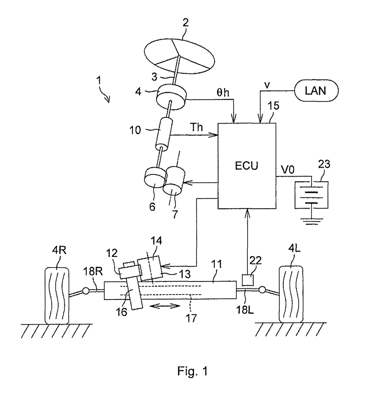
[0024]FIG. 1 is a view showing the overall configuration of a vehicle steering system 1. The vehicle steering system 1 includes a shaft 3, a steering angle sensor 4, a steering torque sensor 10, and a reaction motor 7, A steering member 2 is coupled to the shaft 3. The steering angle sensor 4 is arranged on the shaft 3, and detects a steering angle θh of the steering member 2. The steering torque sensor 10 detects a steering torque Th of the steering member 2. The reaction motor 7 applies a steering reaction force to the steering member 2 via a gear 6. The steering torque sensor 10 detects the steering torque Th by detecting a torsional angle of a torsion bar arranged at a middle portion of the shaft 3. The steering angle sensor 4 detects a rotation angle of the shaft 3 by detecting a magnetism of a multi-polar magnet, which is attached to the outer periphery of the shaft 3,...


PUM


Abstract

When a vehicle is quickly steered while the vehicle is travelling at an extremely low speed, a load on an in-vehicle power supply is reduced without deteriorating a steering feeling by reducing a motor driving current. A steering speed is compared with a threshold. When the steering speed is lower than the threshold, the process proceeds to step S6. In step S6, a voltage value of a battery power supply, which is used as a prescribed value, is set as a limit voltage in order to reduce a motor consumption current. When the steering speed is higher than the threshold, a value “V0 / n” lower than the prescribed value is set as the limit voltage to reduce a consumption current when the steering wheel is steered without driving. “n” is “delay adjustment parameter”, and is a real number that exceeds 1.

Description

INCORPORATION BY REFERENCE / RELATED APPLICATION[0001]This application claims priority to Japanese Patent Application No. 2011-273472 filed on Dec. 14, 2011 the disclosure of which, including the specification, drawings and abstract, is incorporated herein by reference in its entirety.BACKGROUND OF THE INVENTION[0002]Field of the Invention[0003]The invention relates to a vehicle steering system.[0004]Discussion of Background[0005]An electric power steering system, which is an example of a vehicle steering system, is a system that executes appropriate steering assist control in the following manner. A steering torque that is applied to a steering wheel (steering member) and a vehicle speed are detected, a steering torque signal and a vehicle speed signal are transmitted to an EPS electric motor control circuit, and the EPS electric motor control circuit supplies a driving current, which corresponds to the steering torque and the vehicle speed that are obtained from these signals, to a ...

Claims


Application Information

Patent Timeline
Patent Type & Authority Patents(United States)
IPC IPC(8): B62D6/02B62D5/00
CPCB62D5/001B62D6/02
Inventor SUGIYAMA, TOYOKIYOSHII, YASUYUKI
Owner JTEKT CORP
Why Eureka
Try Eureka