Polarization conversion element and optical device

Active Publication Date: 2018-04-24
DEXERIALS CORP
View PDF23 Cites 0 Cited by
  • Summary
  • Abstract
  • Description
  • Claims
  • Application Information

AI Technical Summary

Benefits of technology

The present invention uses a special adhesive and a specific type of plate to create a bond that improves heat and light resistance. The first and second light transmitting members are bonded together using a silicone adhesive, and an inorganic ½ wavelength plate is used that is coated with a dielectric material. This results in improved performance for the device.

Problems solved by technology

However, polarization conversion elements using a UV curing-type adhesive quickly deteriorate with heat and light due to higher brightness of recent transmissive liquid crystal projectors and the like, thereby causing a problem with durability.
For example, when burning occurs at a coating position in association with deterioration of the UV curing-type adhesive in a polarization conversion element, irradiation light is concentrated at the burning position, thereby causing a concern about a decrease in transmittance and the breakage of the element due to a high temperature.
The retardation plate including the polymer stretched film easily deteriorates with heat and UV light and thus has low durability.
Also, since the retardation plate includes the polymer stretched film formed by stretching, this type of retardation plate generally easily contracts.
In addition, the polyvinyl alcohol-based film uses a hydrophilic polymer and is thus easily deformed, particularly, under humidified conditions, and the mechanical strength as a device is weakened.
Although a retardation element having an inorganic optical single crystal such as quartz or the like may be used for solving the problem, there is the problem of difficulty in increasing the size and of high raw material cost and processing cost.

Method used


Image

  • Polarization conversion element and optical device
  • Polarization conversion element and optical device
  • Polarization conversion element and optical device

Examples


example 1

1-5. Example 1

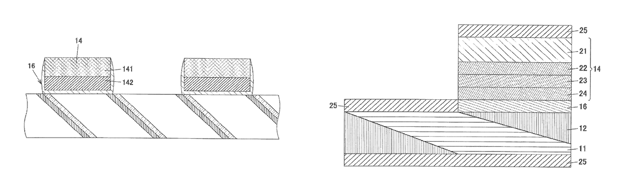
[0066]FIG. 9 is a cross-sectional view showing a configuration of example 1 of the polarization conversion element. In the polarization conversion element shown as example 1, the light-transmitting member of the polarizing beam splitter 11, the light-transmitting member of the reflecting prism 12, and the substrate of the inorganic ½ wavelength plate 14 are made of a glass substrate having a refractive index n of 1.46.

[0067]The inorganic ½ wavelength plate 14 includes a glass substrate 21, a first refractive-index adjusting layer 22, an obliquely deposited layer 23, and a second refractive-index adjusting layer 24, which are laminated in that order. Also, the obliquely deposited layer 23 side as the bond surface of the inorganic ½ wavelength plate 14 is bonded through the second adhesive layer 16 composed of a silicone-based adhesive (n: 1.41).

[0068]In the polarization conversion element shown as example 1, the incident surface of the polarizing beam splitter array 13 ...

example 2

1-6. Example 2

[0070]FIG. 10 is a cross-sectional view showing a configuration of example 2 of the polarization conversion element. Like in example 1, in the polarization conversion element shown as example 2, the light-transmitting member of the polarizing beam splitter 11, the light-transmitting member of the reflecting prism 12, and the substrate of the inorganic ½ wavelength plate 14 are made of a glass substrate having a refractive index n of 1.46.

[0071]The inorganic ½ wavelength plate 14 includes a glass substrate 31, a refractive-index adjusting layer 32, and an obliquely deposited layer 33, which are laminated in that order. Also, the glass substrate 31 side as the bond surface of the inorganic ½ wavelength plate 14 is bonded through the second adhesive layer 16 composed of a silicone-based adhesive (n: 1.41).

[0072]In the polarization conversion element shown as example 2, the outgoing surface of the polarizing beam splitter 11 and the outgoing surface of the inorganic ½ wave...

example 3

1-7. Example 3

[0074]FIG. 11 is a cross-sectional view showing a configuration of example 3 of the polarization conversion element. Like in example 1, in the polarization conversion element shown as example 3, the light-transmitting member of the polarizing beam splitter 11, the light-transmitting member of the reflecting prism 12, and the substrate of the inorganic ½ wavelength plate 14 are made of a glass substrate having a refractive index n of 1.46.

[0075]The inorganic ½ wavelength plate 14 includes a glass substrate 41, a refractive-index adjusting layer 42, an obliquely deposited layer 43, a refractive-index adjusting layer 44, and a SiO2 film 45, which are laminated in that order. Also, the glass substrate 41 side as the bond surface of the inorganic ½ wavelength plate 14 is bonded through the second adhesive layer 16 composed of a silicone-based adhesive (n: 1.41).

[0076]In the polarization conversion element shown as example 2, the outgoing surface of the polarizing beam split...


PUM

PropertyMeasurementUnit
Refractive indexaaaaaaaaaa

Abstract

This invention provides a polarization conversion element that is highly resistant to the heat and light that result from increased brightness levels. In said polarization conversion element, which is provided with a polarizing beam-splitter array in which polarizing beam splitters having polarization separation layers and reflecting prisms having reflective layers are bonded together in alternation, said polarizing beam splitters and reflecting prisms are bonded together by first adhesive layers each comprising a silicone adhesive.

Description

TECHNICAL FIELD[0001]The present invention relates to a polarization conversion element that converts light having random polarization directions to light having one polarization direction, a method for manufacturing the same, and an optical device including the same.BACKGROUND ART[0002]In recent years, each of the devices constituting liquid crystal display apparatuses has been required to have high reliability and durability with increasing applications and functions of liquid crystal display apparatuses. For example, when a light source having a large quantity of light is used as in a transmissive liquid crystal projector, a polarization conversion element that converts natural light emitted from the light source to linearly polarized light receives strong radiation. Therefore, when the polarization conversion element has low durability, an illumination efficiency is decreased.[0003]A polarization conversion element generally includes a polarizing-beam splitter array in which pol...

Claims


Application Information

Patent Timeline
IPC IPC(8): G02B5/30G02B27/28C09J5/00B32B37/12
CPCG02B5/3083C09J5/00G02B27/283G02B27/286C09J2483/00B32B37/1284B32B2307/42
Inventor SASAKI, KOJISASAKI, MASATOSHIKOIKE, NOBUYUKITAKADA, AKIO
Owner DEXERIALS CORP
Why Eureka
Try Eureka