Membrane filter system

a membrane filter and membrane technology, applied in the field of membrane filter systems, can solve the problems of reducing the efficacy reducing reducing the efficiency of the membrane filter, so as to increase enhance the effect of joining and forming a larger bubble or a slug bubble, and improve the useful period of the membrane surfa

Active Publication Date: 2018-05-01
BIONEST TECH
View PDF15 Cites 0 Cited by
  • Summary
  • Abstract
  • Description
  • Claims
  • Application Information

AI Technical Summary

Benefits of technology

[0011]The present invention reduces the difficulties and disadvantages of the aforesaid designs by providing a guide member for directing gas bubble flow along a membrane surface for effective gas scouring.
[0015]Advantageously, the diverting means is arranged to impart different velocities on the gas bubbles directed in the first and second directions. When gas bubbles having different velocities meet, their chances of merging to form a larger gas bubble or preferably a slug bubble is enhanced. Therefore, gas bubbles of different velocities from adjacent guide members can meet to form slug bubbles which flow along the channel(s) to scour the membrane surface(s). It is thought that slug bubbles flowing, against the membrane surface will create a ‘Taylor Effect’ to efficiently remove debris from the membrane surface.
[0019]Advantageously, the guide member further comprises an attachment means for detachably attaching the guide member to a housing, to another guide member or to a membrane module. The attachment means comprises at least one tab extending from the second side edge, the tab having an opening. In one embodiment, the attachment means comprises two tabs, each tab having an opening and extending from and spaced along the second side edge. The opening(s) are arranged to receive a bar or a rod which can also extend through corresponding attachment means in the housing or the other guide member or the membrane module. Alternatively, the attachment means can be of any other suitable form such as a bar which extends through openings in the housing or membrane module. This means that the guide member can be easily attached and detached from a membrane module, housing or another guide member for ease of assembly and disassembly.
[0027]Advantageously, the method can further comprise imparting a different velocity on the gas bubbles directed to the first and second membrane surfaces. When gas bubbles with different velocities meet, their chances of joining to form a larger bubble or a slug bubble is enhanced. Slug bubbles are thought to have an effective cleaning effect on a membrane surface against which they flow.
[0028]By means of embodiments of the invention, a guide member can be placed adjacent and touching a membrane surface to provide a path or paths for gas bubbles to flow along and scour. An array or stack of membrane modules separated by guide members can be provided whereby the channel(s) of each guide member can guide the movement of gas bubbles across two adjacent and oppositely facing membrane surfaces. The diverting means of the guide member can impart different velocities on incident gas bubbles. Therefore, at each channel bottom end there will be gas bubbles with different velocities which will meet to form slug bubbles within the channel(s). As the channel(s) cover the entire, or practically the entire, membrane surface, the gas bubbles will scour and clean the entire, or practically the entire, membrane surface. This will increase the useful period of a membrane surface and reduce the frequency of maintenance and repair thereby reducing operating costs and minimizing costs. The guide member also provides support to the membrane surface to allow backwashing. Regular backwashing can help maintain the membrane surface free of debris and minimize downtime where the membrane surface must be removed and cleaned.

Problems solved by technology

This membrane fouling decreases the flow of the wastewater through the membrane filter and gradually reduces the efficacy of the membrane filter until it must be replaced or cleaned.
This can lead to down-time of the treatment process which is both costly and inconvenient and increases operating costs.
A problem with the scouring method is that gas bubbles take a path of least resistance across the membrane surface as they rise.
However, the gas bubbles may still take the path of least resistance as they rise across the membrane surfaces thereby leaving parts of the membrane surfaces unscoured.

Method used


Image

  • Membrane filter system
  • Membrane filter system
  • Membrane filter system

Examples


Embodiment Construction

[0052]This invention is not limited in its application to the details of construction and the arrangement of components set forth in the following description or illustrated in the drawings. The invention is capable of other embodiments and of being practiced or of being carried out in various ways. Also, the phraseology and terminology used herein is for the purpose of description and should not be regarded as limiting. The use of “including”, “comprising”, or “having”, “containing”, “involving” and variations thereof herein, is meant to encompass the items listed thereafter as well as, optionally, additional items.

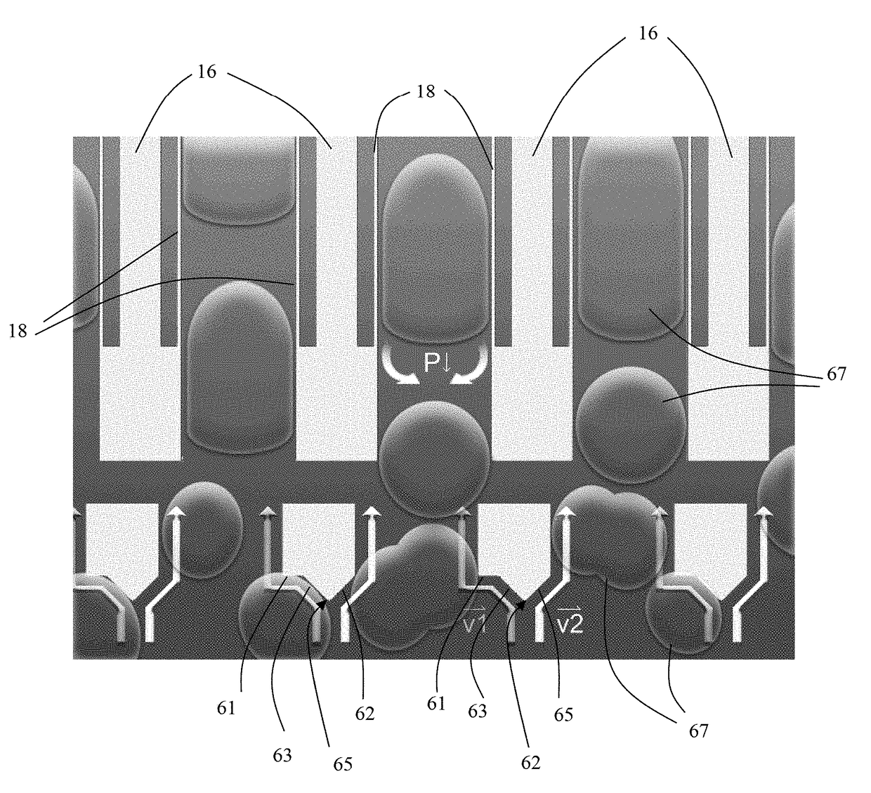
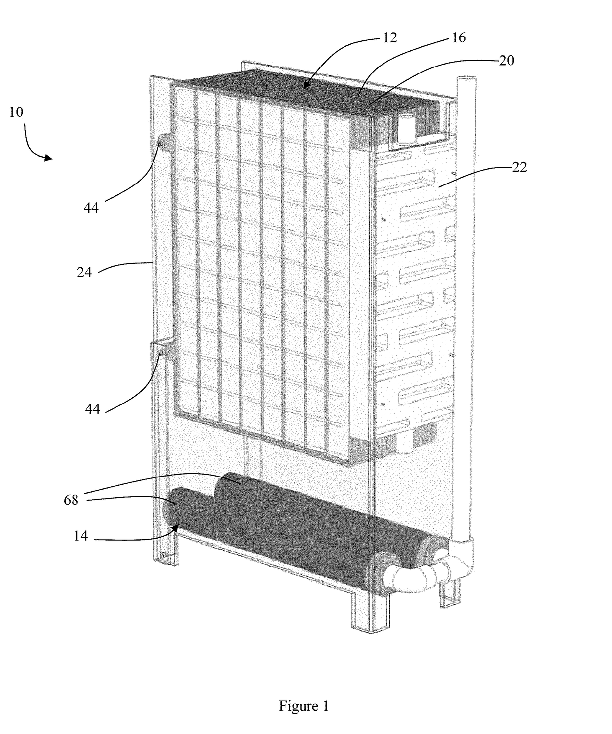
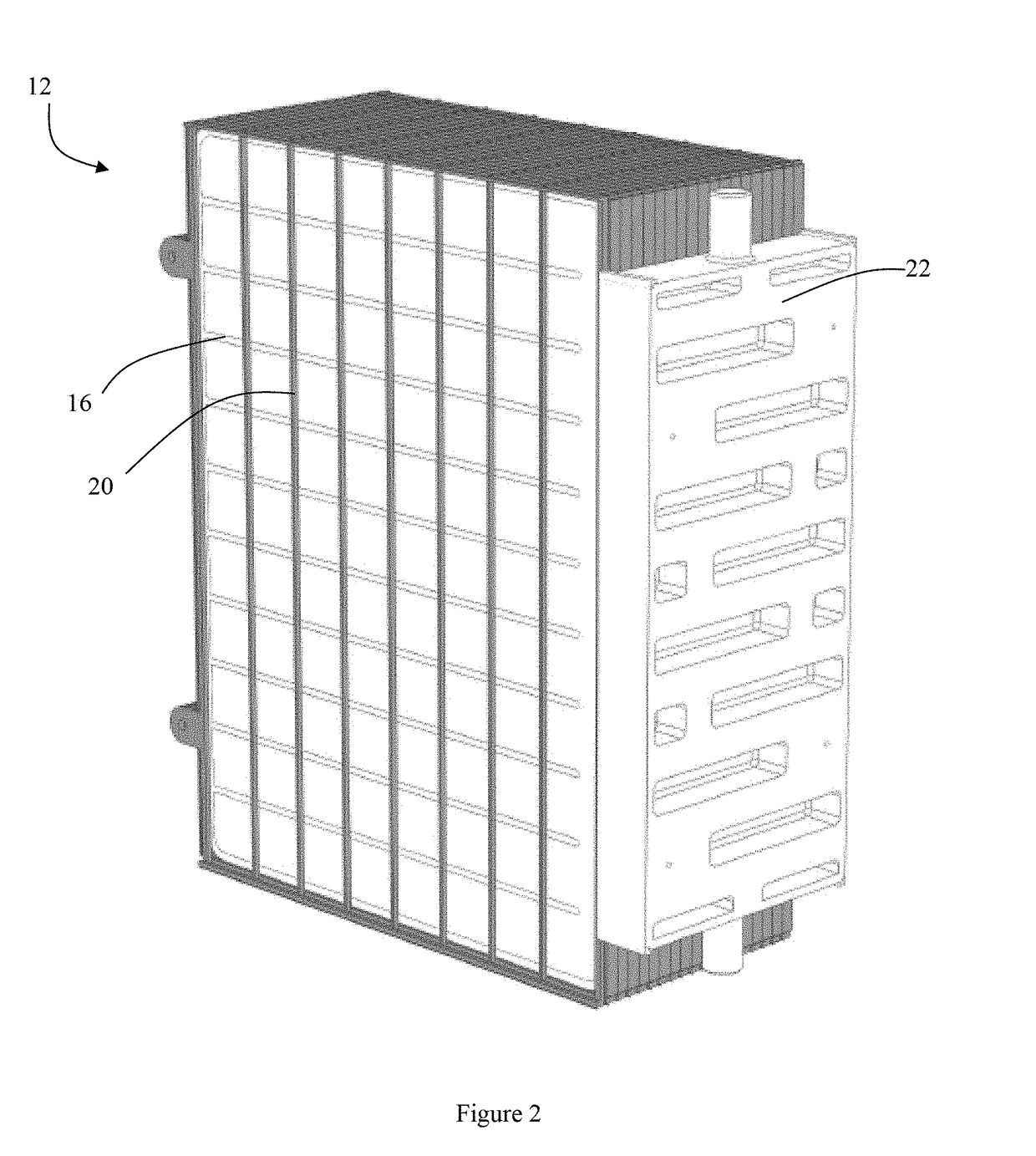
[0053]With reference to FIG. 1, a membrane filter system according to one embodiment of the present invention is generally illustrated at 10. The membrane filter system 10 broadly comprises a membrane module assembly 12 for treating water such as wastewater and a gas bubble generation (aeration) system 14 for producing gas bubbles and supplying them to the membrane modul...


PUM

PropertyMeasurementUnit
widthaaaaaaaaaa
pore sizeaaaaaaaaaa
depthaaaaaaaaaa

Abstract

A guide member for directing gas bubble flow along a membrane surface, the guide member having first and second side edges defining a channel for gas bubbles to flow along, the channel having an open bottom end through which the gas bubbles can enter the channel and an open top end through which the bubbles can exit the channel, and a diverting means adjacent the channel bottom end arranged to direct at least some of the incident gas bubbles in a first direction towards the channel bottom end. A membrane module assembly and a membrane filter system including the guide member.

Description

[0001]This application is the U.S. National Stage filing under 35 U.S.C. § 371 of International Application Serial No. PCT / CA2011 / 000307 filed Mar. 23, 2011, which claims priority to U.S. Provisional Application No. 61 / 317,023 filed Mar. 24, 2010, each of which is incorporated herein by reference in its entirety.FIELD OF THE INVENTION[0002]The present invention generally relates to membrane filter systems and more specifically, though not exclusively, to submerged flat sheet membrane filter systems and membrane module assemblies.BACKGROUND OF THE INVENTION[0003]Membrane filters are commonly used in domestic and industrial water treatment systems to separate solids from liquids. Not only are they used to treat wastewater but they are also used to improve the water quality of lakes, ponds and rivers. A typical wastewater treatment system includes the biological decomposition of the wastewater using microbes in a bioreactor followed by the filtration of the decomposed wastewater throug...

Claims


Application Information

Patent Timeline
Patent Type & Authority Patents(United States)
IPC IPC(8): B01D65/02B01D61/18B01D61/20C02F3/12B01D63/08C02F1/44
CPCB01D61/18B01D61/20B01D63/082C02F3/1273B01D2313/08Y02W10/15B01D2315/06B01D2321/185C02F1/442C02F1/444C02F2303/16B01D2313/26Y02W10/10B01D63/0822
Inventor LORD, GARFIELD R.
Owner BIONEST TECH
Why Eureka
Try Eureka