Thyristor controlled LC compensator for compensating dynamic reactive power

a dynamic reactive power and compensator technology, applied in the direction of electric power transfer ac network, harmonic reduction/ripple reduction, etc., can solve the problems of increasing operating costs or reducing transmission capacity, reactive power is a major issue, and the development of a smart grid presents many new challenges with respect to power quality

Active Publication Date: 2018-05-01
UNIVERSITY OF MACAU
View PDF3 Cites 14 Cited by
  • Summary
  • Abstract
  • Description
  • Claims
  • Application Information

AI Technical Summary

Benefits of technology

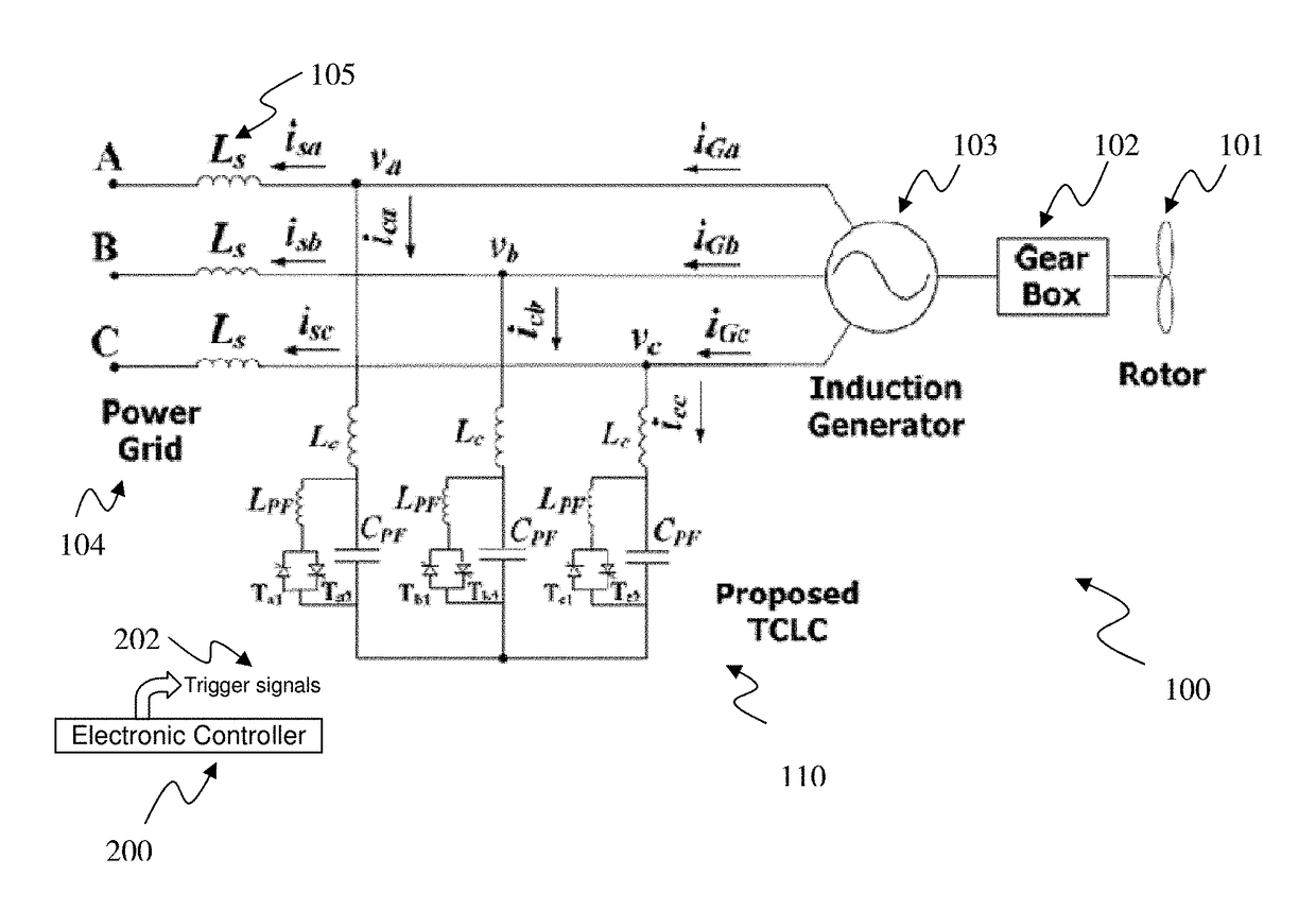
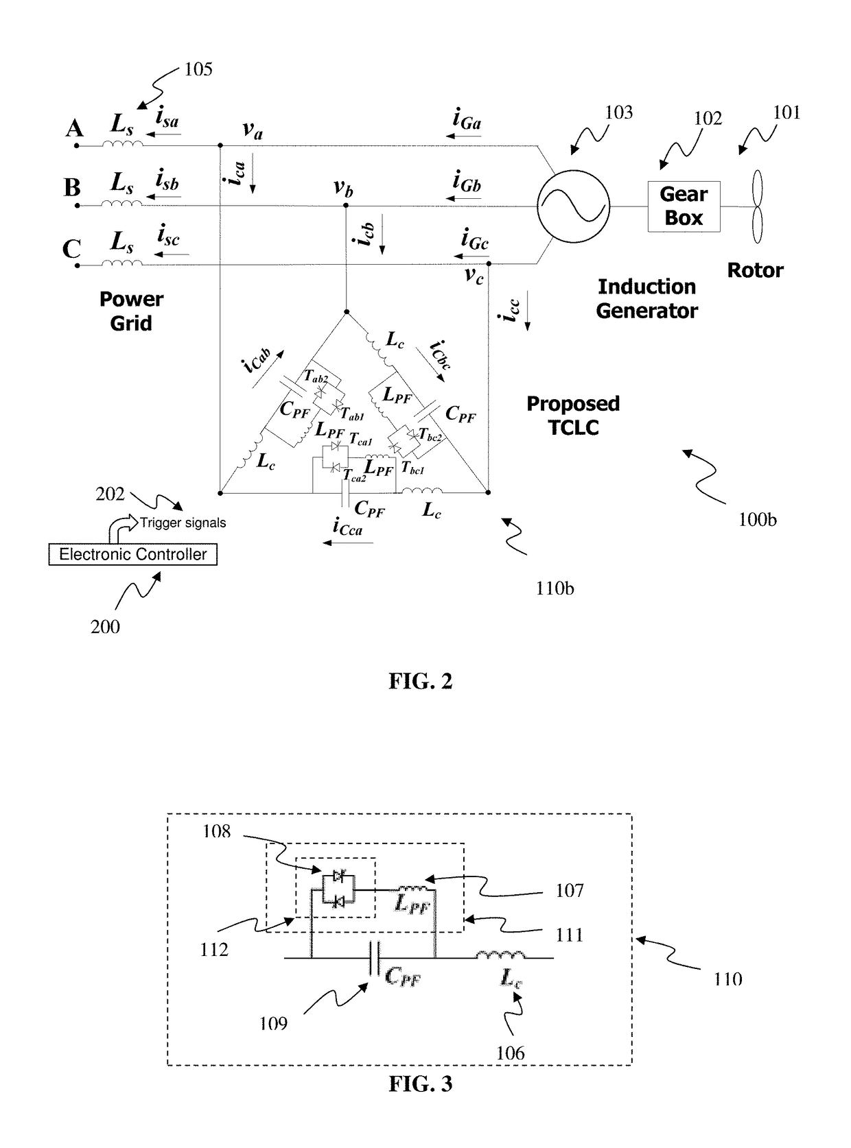
[0008]Accordingly, a thyristor controlled LC (TCLC) compensator for compensating dynamic reactive power in a power grid system is provided. The TCLC compensator comprises three branches of sub-circuit, each branch of sub-circuit having a first branch-terminal and a second branch-terminal and an electronic controller for controlling the solid-state bidirectional switch of each branch of sub-circuit and determining when to switch on the solid-state bidirectional switch. Each branch of sub-circuit further comprises a controllable reactor (CR) comprising a parallel inductor (LPF) connected in series with a solid-state bidirectional switch; a coupling inductor (Lc) having a first terminal and a second terminal, the first terminal being connected to a line in the power grid system and the second terminal being connected to the CR; and a parallel capacitor (CPF) connected in parallel to the CR. The coupling inductor (Lc) is determined according to a harmonic order (n) of the harmonic current generated to the line in the power grid system by the solid-state bidirectional switch in the TCLC compensator such that the harmonic current is mitigated, where n is selected such that the selected n is smaller than 5, so that the harmonic current generated under the selected resonance order n is less than 50% of the harmonic current generated under n=5; and the selected n is greater than 1.5 (n>1.5) so that an inductance of the coupling inductor (Lc) under the selected n is less than 50% of an inductance of the coupling inductor (Lc) under n=1.5 (XL<sub2>c< / sub2>(n)≤0.5·XL<sub2>c < / sub2>(n=1.5)).

Problems solved by technology

However, the development of a smart grid presents many new challenges with respect to power quality [1].
In particular, reactive power has been a major issue.
Large reactive power draws more reactive current which results in either an increase in the operating cost or a decrease in the transmission capacity.
However, during the operation of the FC-TCRs, low-order harmonic currents are generated, which can deteriorate system performance.
However, a STATCOM system is more expensive than SVC at the same VA power rating.
Therefore, this topology failed to replace the older SVC technology.
However, the oscillating time and cost of this approach are both significantly higher.
However, considering the complexity of the system, the initial cost of this approach can be very high.
However, as the firing angles are probably not matched with the required compensating reactive power, the TCR-TSC may sacrifice its reactive power compensation capability.

Method used


Image

  • Thyristor controlled LC compensator for compensating dynamic reactive power
  • Thyristor controlled LC compensator for compensating dynamic reactive power
  • Thyristor controlled LC compensator for compensating dynamic reactive power

Examples


Embodiment Construction

[0052]The following definitions are used herein in the specification and the appended claims. “TCLC compensation system” is used to represent a three-phase three-wire power grid system with a TCLC compensator, disclosed herein, connected thereto for compensating for reactive power. “Power grid system” is an interconnected network for delivering electricity from an electricity-generation source to consumers, wherein the electricity-generation source is referred as a “power source”. An example of the power source is a renewable energy source. The preferred application of the present disclosure is wind farm. In certain embodiments, the power grid system is a three-phase system in electricity transmission. Practically, it is common that three phases are used in the power grid system. “System frequency” is the line frequency or nominal frequency of the oscillations of alternating current (AC) in a power grid system, which is typically at 50 Hz or 60 Hz. “Line” in a power grid means any o...


PUM


Abstract

A thyristor controlled LC (TCLC) compensator for compensating dynamic reactive power in a power grid system, with an advantage of mitigating harmonic current injection from solid-state switches during switching on or off is provided. Exemplarily, the TCLC compensator is shunt-connected to the three-phase power grid and comprises an electronic controller, a coupling inductor (Lc), a first branch of circuit with a parallel inductor (LPF) and a solid-state switch, and a second branch of circuit with a parallel capacitor (CPF), wherein the coupling inductor (Lc) is connected in series with a parallel combination of the first and second branch of circuit. The electronic controller for the TCLC compensator is configured in accordance to the generalized instantaneous reactive power theory for improving the response speed instead of using traditional average reactive power concept.

Description

FIELD OF THE INVENTION[0001]The present invention generally relates to compensating dynamic reactive power in a power grid system by a thyristor controlled LC (TCLC) compensator. In particular, the present invention relates to a design method, a control method and a system for dynamic reactive power compensation with an advantage of mitigating harmonic current injection from solid-state switches during switching on or off.PRIOR DISCLOSURES BY THE INVENTOR OR A JOINT INVENTOR[0002]Part of the present invention was disclosed in a paper published in the IEEE Transactions on Smart Grid (Volume: 8, Issue: 1, pp. 409-417, January 2017) on 7 Jun. 2016. This paper is a grace period inventor-originated disclosure disclosed within one year before the effective filing date of this application.BACKGROUND OF THE INVENTION[0003]The use of a smart grid connected renewable energy system has been regarded as our next-generation power grid for solving the energy crisis. The smart grid system transfer...

Claims


Application Information

Patent Timeline
Patent Type & Authority Patents(United States)
IPC IPC(8): H02J3/18H02J3/36H02J3/26H02J3/01H02M1/12H02J3/00H02M5/44
CPCH02J3/1821H02J3/01H02J3/36H02J3/26H02J2003/007H02M1/12H02M5/44H02J3/1864H02J2300/24H02J3/381Y02E10/56Y02E40/10H02J3/50H02J3/40
Inventor WANG, LEIWONG, MAN-CHUNGLAM, CHI-SENG
Owner UNIVERSITY OF MACAU
Why Eureka
Try Eureka