Floating oil and gas facility with a movable wellbay assembly

a technology of floating oil and gas facilities and wellbays, which is applied in the direction of floating buildings, special-purpose vessels, transportation and packaging, etc., can solve the problems of affecting the center of gravity and stability of the unit, the idea of converting an existing semi-submerged modu into a floating production facility with dry trees is not generally considered feasible by the industry, and no deep-water field development has been completed

Active Publication Date: 2018-05-22
FRONTIER DEEPWATER APPRAISAL SOLUTIONS LLC
View PDF35 Cites 6 Cited by
  • Summary
  • Abstract
  • Description
  • Claims
  • Application Information

AI Technical Summary

Problems solved by technology

“State of the art for dry tree semi technologies”, by Yu Hao et al, Engineering Science, 2013) but none have been built for deep water field development.
The idea of converting an existing semisubmersible MODU into floating production facility with dry trees is not generally considered feasible by industry today due to the inability to move the drilling derrick on the top deck and because of the large heave of these units during extreme storms.
It is readily observed that moving a drilling derrick, all of its associated systems, and suspended loads about on the top deck affects the center of gravity and stability of the unit.
Such a modification to an existing semisubmersible MODU is complex and costly.
It also means that more of the deck area of the unit will be required for drilling operations—meaning that less space is available for oil and gas production equipment.

Method used


Image

  • Floating oil and gas facility with a movable wellbay assembly
  • Floating oil and gas facility with a movable wellbay assembly
  • Floating oil and gas facility with a movable wellbay assembly

Examples


first embodiment

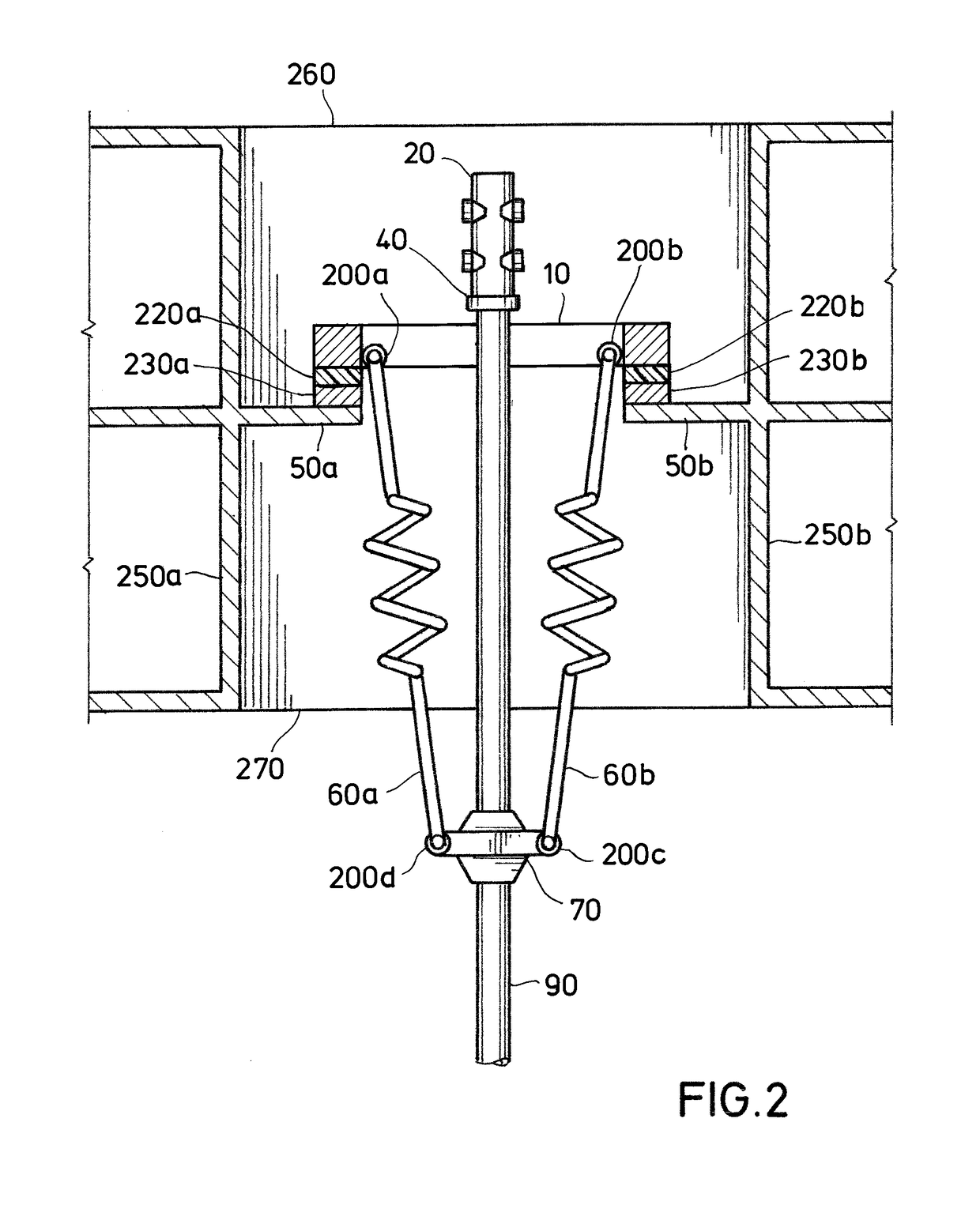
[0050]The movable wellbay structure of the first embodiment in which a structural element, commonly called a “tensioning ring” which incorporates features to avoid stress concentrations and may incorporate extensive framing elements, affixed to or part of a riser joint at the top of each of the top-tensioned riser strings supported by said movable wellbay structure is securely guided by a geared track or sliding contact with a rigid beam or rail built in as part of the movable wellbay structure frame structure extending vertically the entire range of stroke of the tensioning devices affixed between said movable wellbay structure and the tensioning ring and / or other guide devices attached to the riser, wherein the friction between the tensioner ring and other devices and the rigid beam or rail of the sliding contact is reduced by treating the contact surface of the tensioner ring's interfacing elements with a low friction coating or by affixing a pad or pads of low friction material ...

embodiment 1

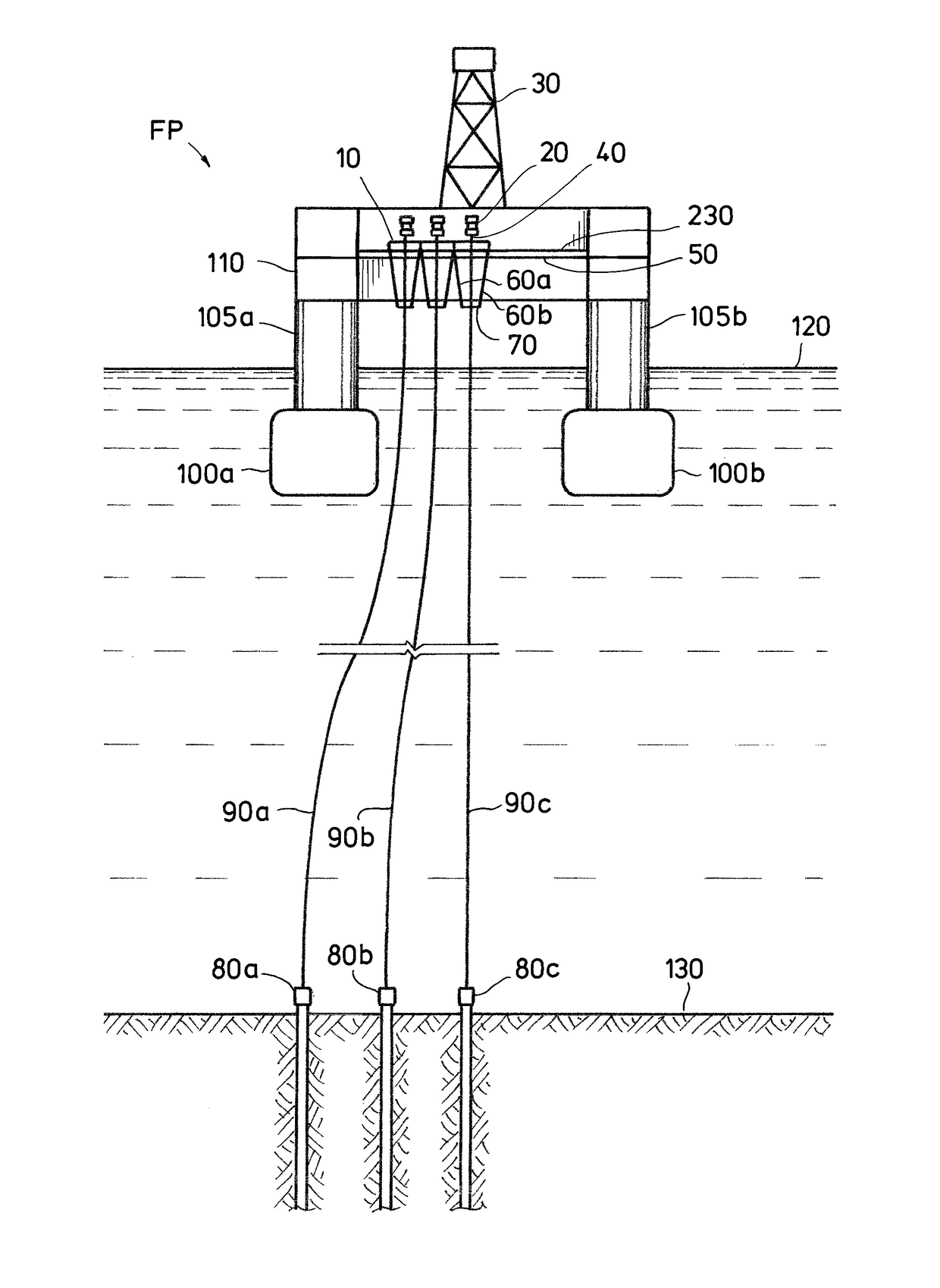
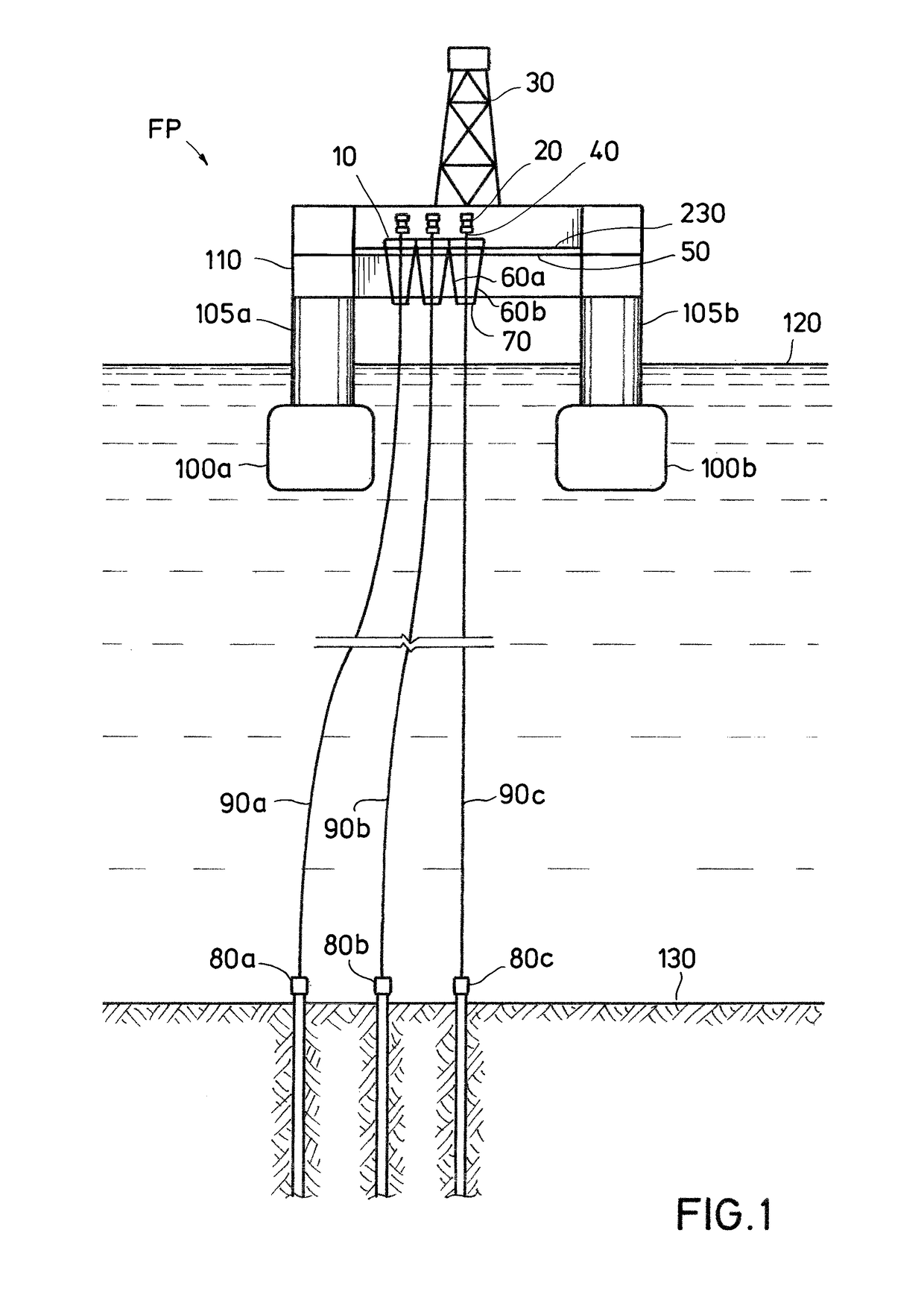
[0080]2. The offshore facility of embodiment 1, where the multiple top tensioned risers enable operations on and production from and vertical access to subsea completed wells with wet trees or surface completed wells with dry trees that have subsea wellheads located on a tight array on the seafloor essentially beneath the floating production facility, possibly where the wellheads are within about 50 feet of each other.

[0081]3. The offshore facility of embodiment 1 or 2, where each riser holder further includes a dynamic top tensioning system for holding a riser in tension.

[0082]4. The offshore facility of embodiment 1, 2 or 3, where the structural assembly is supported by a dynamic tensioning system which uniformly holds all of the more than two top-tensioned risers uniformly in tension when the risers are rigidly connected to the structural assembly.

[0083]5. The offshore facility of any one of embodiments 1-4, where the riser holders for each of the top tensioned risers are arrange...

embodiment 10

[0089]11. The method of embodiment 10, where either the up stroke or down stroke or the range of both the up and the down stroke of the dynamic tensioners supporting the top tensioned risers is limited by placing mechanical stops and shock absorbing systems at desired positions such that the range of movement of the tension rings attached to the top tensioned risers is constrained while any further dynamic displacement of the hull is accommodated by stretching or compressing the risers.

[0090]12. The method of embodiment 10, where either the up stroke or down stroke or the range of both the up and the down stroke of the dynamic tensioners supporting the top tensioned risers is limited by splitting allocation of the targeted stroke range between the tensioners on the wellbay and those on the individual risers.

[0091]13. A floating oil and gas production platform installed in deep water that includes: a permanent spread mooring supporting a large centrally located drilling derrick with ...


PUM


Abstract

A mobile offshore drilling unit is converted to provide drilling, completion and workover access to multiple dry tree wells from a drilling derrick to allow production and export of oil and gas from high pressure, high temperature reservoirs in deep offshore waters. Existing practice has been for the drilling derrick on a production platform supporting dry tree wells to be moved over a fixed well slot. The present invention provides a movable wellbay that supports multiple top-tensioned subsea well tieback risers, which may be positioned directly below the derrick's rotary table and / or beneath another operating device. The use of top-tensioned subsea well tieback risers supported by the movable wellbay allows the converted facility to drill, complete, maintain, improve and produce from subsea wells through dry trees.

Description

CROSS REFERENCE TO RELATED APPLICATIONS[0001]This application claims priority to and the benefit of U.S. Provisional Patent Application Ser. No. 62 / 384,626 filed on Sep. 7, 2016, which is incorporated by reference.BACKGROUND OF THE INVENTION1. Field of the Invention[0002]This application relates generally to offshore oil and gas wells and other subterranean exploration and production activities and more specifically to floating production systems built or made by converting mobile offshore drilling units (MODUs) to include a movable wellbay structure and a multi-well dry-tree production system that enables drilling, evaluation, completion, and maintenance of offshore wells.2. Description of the Related Art[0003]U.S. Pat. No. 5,150,987, issued to White et al., describes a heave-restrained platform and drilling system (HRP / DS) for drilling and producing through oil wells in deep water that included a floating structure having a central buoyancy means, at least three out-rigger columns...

Claims


Application Information

Patent Timeline
Patent Type & Authority Patents(United States)
IPC IPC(8): E21B19/00B63B35/44E21B15/02B63B21/20
CPCE21B19/006B63B21/20E21B15/02B63B35/4413B63B2021/203E21B7/12E21B17/01E21B19/004
Inventor SHILLING, III, ROY B.WHITE, CHARLES N.DAY, HOWARD W.F.
Owner FRONTIER DEEPWATER APPRAISAL SOLUTIONS LLC
Why Eureka
Try Eureka