Tank

a tank system and tank body technology, applied in the field of tanks or tanks, can solve the problems of low pressurization possible on the tank, partial load, inadmissible, etc., and achieve the effect of improving the insulation effect, increasing the vehicle load, and positive effect on the heat penetration into the tank

Active Publication Date: 2018-05-22
AIRBUS DS
View PDF12 Cites 0 Cited by
  • Summary
  • Abstract
  • Description
  • Claims
  • Application Information

AI Technical Summary

Benefits of technology

[0016]Achieved as a result is a reduction in the evaporation rates. This reduction combined with a higher charging of liquid distinctly improves the efficiency of the transportation means.
[0022]In particular, the anchors form a strong and releasable connection due to a spring mechanism. As a consequence, the frame structures can be assembled or disassembled very quickly and easily.
[0025]In a special embodiment of the invention, the tank exhibits a plurality of containers which are arranged in a row side by side and separated from one another by an intermediate region. This increases the vehicle load.
[0026]In the embodiment just mentioned, the arrangement for feeding and discharge liquids and the arrangement for feeding and discharging gases are arranged in the intermediate region of two adjacent containers, so as to introduce the fewest possible baffles into the tank, which has a positive effect on the heat penetrating into the tank.

Problems solved by technology

However, the disadvantage here is that partial loads, e.g., between a 10% and 70% fill level, are not permissible, since the arising sloshing movements of the liquid can damage the tank walls.
In addition, the pressurization possible on the tank is low.
As opposed to when being stored in spherical tanks, they are therefore not supercooled in their saturation state during transport, and thus impaired by elevated evaporation losses.
The efficiency of liquid transport and potentially the burden on the environment depend heavily on the evaporation losses.
In actual fact, the heat bridges this produces are not conducive to the insulating effect of the tank.
If these surfaces are briefly wetted with liquid by sloshing movements, this increases the evaporation rate.
Additional losses due to thermal radiation as well as thermal conduction through the gas result in elevated evaporation losses.
In the type at hand, however, its implementation is not suitable in a ship tank for transporting liquids in membrane tanks.

Method used


Image

  • Tank
  • Tank
  • Tank

Examples


Embodiment Construction

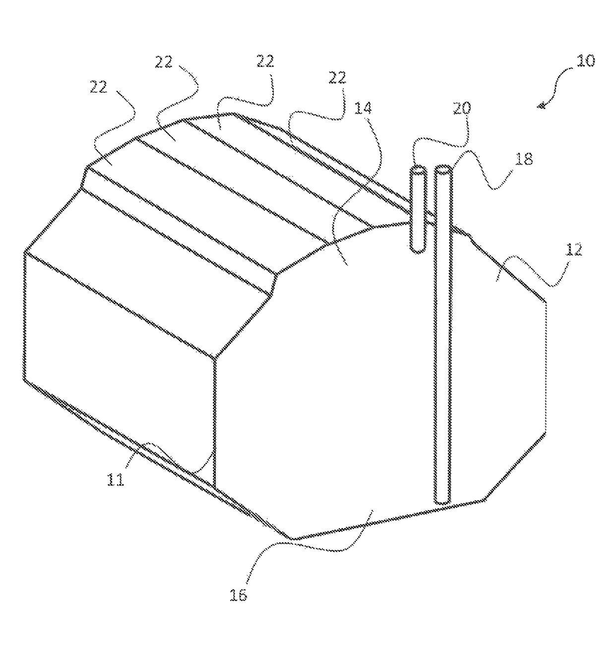
[0043]FIG. 4 illustrates a tank or tank system 10 with a prismatic shape 11 for storing a cryogenic liquid. The tank 10 exhibits a collecting container 12 with an upper region 14 and a lower region 16. The tank 10 further exhibits at least one arrangement 18 for feeding and discharging liquids and at least one arrangement 20 for feeding and discharging gases. As evident from the figure, the upper region 14 is divided into pieces of flat surfaces 22. This yields an additional volume 24 (FIG. 5) in the upper region 14 of the container 12.

[0044]As shown in particular on FIG. 5, layered surfaces or frame structures 26 are horizontally secured in the additional volume 24. The surfaces 26 are held on the upper region 14 of the container 12 by vertical pipes 27 and additional fixing means 28. The number of surfaces 26 can vary by tank 10. The surfaces 26 comprising frame structures 26 (FIG. 7), whose size is easy to handle during tank manufacture.

[0045]FIG. 6 shows a special embodiment of ...


PUM


Abstract

A tank or tank system for storing a cryogenic liquid exhibiting at least one collecting container with an upper region and a lower region, so as to hold the cryogenic liquid, at least one arrangement for feeding and discharging liquids and at least one arrangement for feeding and discharging gases, wherein the tank further exhibits at least one frame structure comprising a thermal insulation material.

Description

CROSS-REFERENCES TO RELATED APPLICATIONS[0001]This application claims the benefit of the European patent application No. 15193782.8 filed on Nov. 10, 2015, the entire disclosures of which are incorporated herein by way of reference.BACKGROUND OF THE INVENTION[0002]The invention relates to a tank or a tank system, in particular to a tank for transporting cryogenic liquids in tankers.[0003]The transport of liquid gasses by water has in the meantime developed into a sophisticated branch of industry, which has at its disposal a large fleet of tankers, a network of export and import terminals, along with a wealth of knowledge and experience from the various individuals participating in the processes. Gas tankers are equipped with specific features that they share with other tankers used for conveying bulk liquid cargoes, such as oil and chemicals.[0004]Liquid tankers today represent a flexible alternative to the transport of liquid gas in pipelines, and are used for the maritime transpor...

Claims


Application Information

Patent Timeline
Patent Type & Authority Patents(United States)
IPC IPC(8): F17C1/00F17C3/04F17C1/12
CPCF17C3/04F17C1/12F17C2270/0168F17C2201/0157F17C2201/052F17C2203/012F17C2203/014F17C2203/015F17C2203/032F17C2203/0304F17C2203/0358F17C2205/013F17C2221/033F17C2221/035F17C2223/0161F17C2223/033F17C2223/045F17C2223/047F17C2260/033F17C2270/0105F17C1/002F17C3/025F17C13/00F17C13/082F17C2201/054F17C2270/0102F17C2260/016Y02E60/32B65D90/022B65D88/128B63B25/08B63B25/16
Inventor BEHRUZI, KEI-PHILIPPDE ROSE, FRANCESCO
Owner AIRBUS DS
Why Eureka
Try Eureka