Full characterization wavefront sensor

Active Publication Date: 2018-05-22
BEAM ENG FOR ADVANCED MEASUREMENTS
View PDF134 Cites 27 Cited by
  • Summary
  • Abstract
  • Description
  • Claims
  • Application Information

AI Technical Summary

Benefits of technology

The present invention provides sensors, devices, apparatus, systems, and methods that can replace non-switchable microlens arrays with one or more switchable diffractive waveplate microlens arrays. This helps to measure wavefronts with a wider range of characteristics, allowing for more complete characterization of optical wavefronts.

Problems solved by technology

Although the prior art wavefront sensors, including Shack-Hartmann wavefront sensors, allow for extensive and useful characterization of optical beams, these sensors are limited in their wavefront sensing capability due to limitations imposed by two major factors.
The first factor is the limitation on spatial resolution of the microlens array used in these sensors.
The second factor is the limitation on angular resolution imposed by the focal length of the microlenses composing the microlens array, combined with the pitch of the CCD, CMOS, or other image sensor used to detect the optical beam.
The spatial resolution cannot be indefinitely increased by the manufacturer because reducing the pitch (thus obtaining a higher spatial resolution) while keeping the microlens focal length constant also reduces the range of wavefront slopes measureable by the wavefront sensor.
The angular resolution of the wavefront sensor cannot be indefinitely increased by the manufacturer by increasing the focal length of the microlenses because increasing the focal length (thus obtaining greater angular resolution) while keeping the pitch of the microlens array constant also reduces the range of wavefront slopes measureable by the wavefront sensor.
A fixed microlens array with fixed pitch and fixed focal length will not be optimal for every wavefront measurement task encountered by users.
Typically, a lengthy and difficult calibration procedure must be performed each time the microlens array is removed and replaced.
The process of removing and replacing the microlens array thus becomes time-consuming and expensive.
However, as noted above, removing and replacing the microlens array is, if it is possible at all, a time-consuming and expensive process.

Method used


Image

  • Full characterization wavefront sensor
  • Full characterization wavefront sensor
  • Full characterization wavefront sensor

Examples


first embodiment

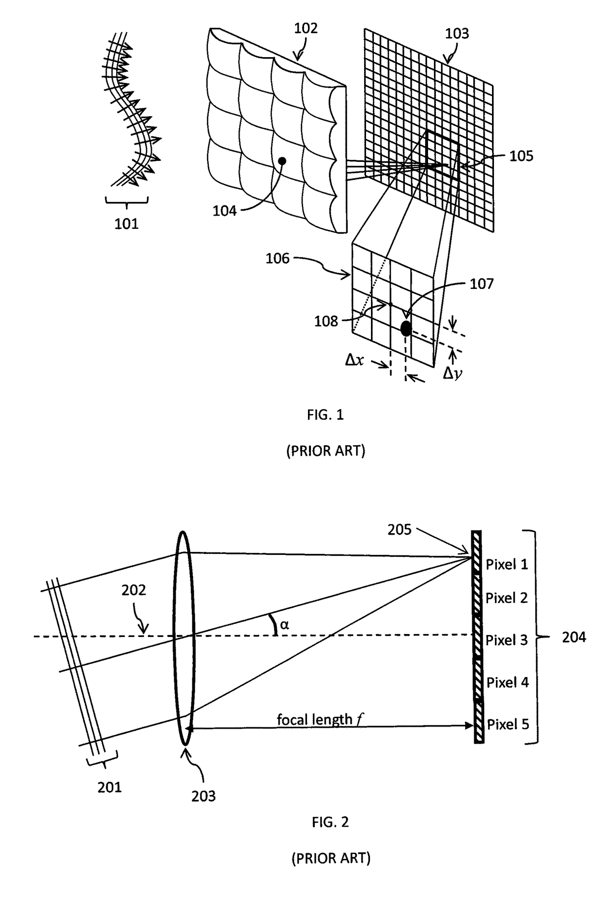
[0075]As the present invention, the fixed, static microlens array 102 of FIG. 1 of the prior art would be replaced with a switchable microlens array. Consecutive measurements would be made with the microlens array switched on for wavefront slope measurements, and with the microlens array switched off for measurements of the spatial distribution of beam power density. This would greatly reduce the spatial sampling period of the beam power density, thereby providing a much more complete spatial beam profile than is provided by Shack-Hartmann wavefront sensors based on prior art.

[0076]As an example, Shack-Hartmann wavefront sensors currently available for purchase, employing CCD or CMOS image sensors, are such that the pitch of the microlens array is 30 to 65 times the pitch of the CCD or CMOS image sensor, and (as previously noted) the spatial sampling period for both wavefront slope and beam power density is equal to the pitch of the microlens array. If the microlens array could be s...

second embodiment

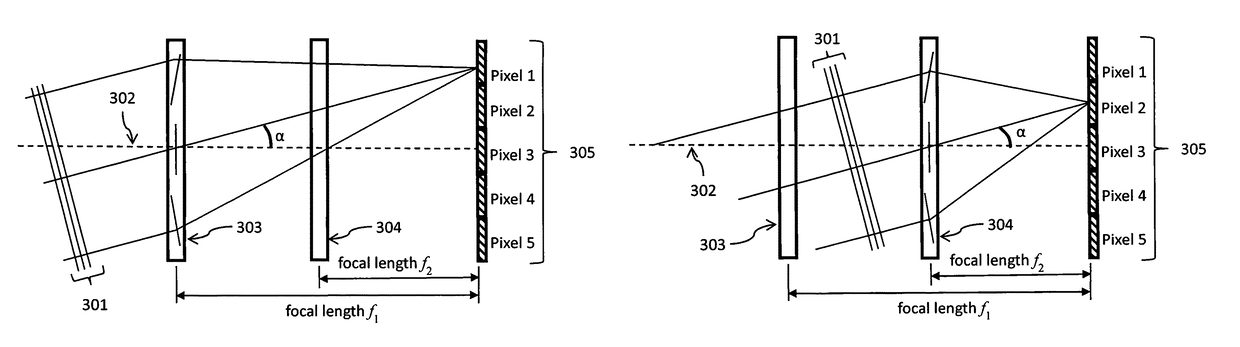
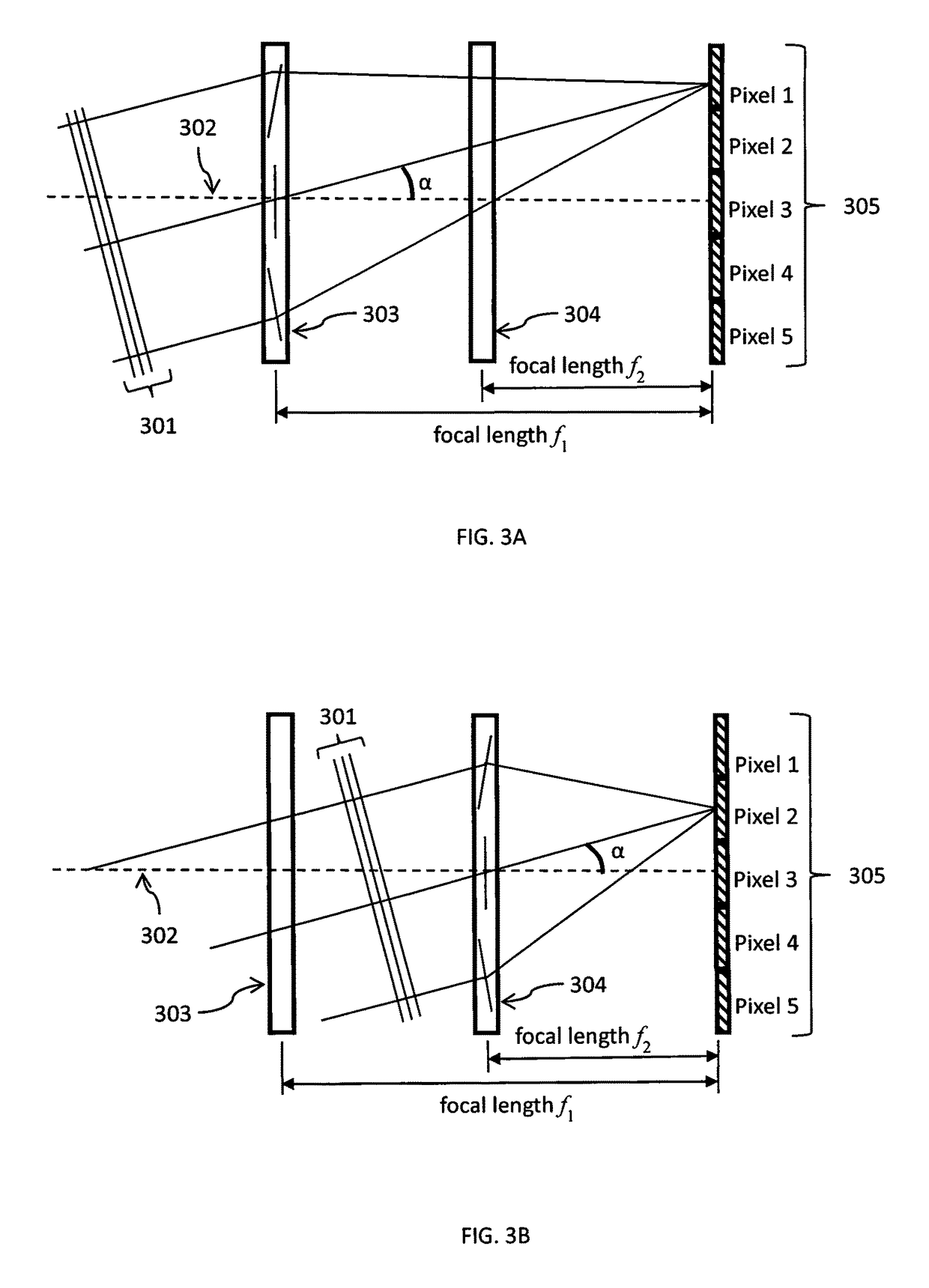
[0080]the present invention is illustrated in FIGS. 4A and 4B. In this embodiment, there are again two switchable microlens arrays as was the case for the embodiment illustrated in FIGS. 3A and 3B. However, for the embodiment illustrated in FIGS. 3A and 3B, the focal lengths of the two microlens arrays are different, whereas in the embodiment illustrated in FIGS. 4A and 4B, the focal lengths of the two microlens arrays are the same.

[0081]Also, for the embodiment illustrated in FIGS. 3A and 3B, the pitches of the two microlens arrays are the same, whereas in the embodiment illustrated in FIGS. 4A and 4B, the pitch of the microlens array that includes microlenses 404 and 405 is half as large as the pitch of the microlens array that includes microlens 403. Therefore, for the embodiment illustrated in FIGS. 4A and 4B, the spatial sampling density of the incoming wavefront slope can be adjusted by switching one or the other of the two microlenses on or off.

[0082]FIGS. 4A and 4B give exam...


PUM


Abstract

Sensors, devices, apparatus, systems and methods for replacing microlens arrays with one or more switchable diffractive waveplate microlens arrays for providing measurements of wavefronts and intensity distribution in light beams with high spatial resolution with a single optical radiation sensor. The device acts like a conventional Shack-Hartmann wavefront sensor when the microlens array elements are in focusing state, and the device performs light beam intensity profile characterization acting as a beam profiler when the optical power of lens array elements is switched off.

Description

CROSS REFERENCE TO RELATED APPLICATIONS[0001]This application claims the benefit of priority to U.S. Provisional Patent Application Ser. No. 62 / 186,622 filed Jun. 30, 2015. The entire disclosure of the application listed in this paragraph is incorporated herein by specific reference thereto.FIELD OF INVENTION[0002]This invention relates to optical sensors, and in particular to sensors, devices, apparatus, systems and methods for laser beam and optics characterization, replacing microlens arrays with one or more switchable diffractive waveplate microlens arrays for providing wavefront and light intensity measurements with higher resolution and wider dynamic range of characteristics than are possible using prior art, thus allowing more complete and precise characterization of optical wavefronts and beam profiles.BACKGROUND AND PRIOR ART[0003]Sensors such as a Shack-Hartmann wavefront sensor are often used to characterize the spatial characteristics of optical wavefronts, including the...

Claims


Application Information

Patent Timeline
IPC IPC(8): G01J9/00
CPCG01J9/00G01J2009/002G01J1/0411G01J1/4257
Inventor TABIRIAN, NELSON V.LIAO, ZHI J.
Owner BEAM ENG FOR ADVANCED MEASUREMENTS
Why Eureka
Try Eureka