Autonomous working system, an autonomous vehicle and a turning method thereof

a working system and autonomous technology, applied in the field of intelligent control, can solve the problems of insufficient coverage scope, inability to rationally, and need a long time to leav

Active Publication Date: 2018-05-29
POSITEC POWER TOOLS (SUZHOU) CO LTD
View PDF19 Cites 9 Cited by
  • Summary
  • Abstract
  • Description
  • Claims
  • Application Information

AI Technical Summary

Benefits of technology

[0114]Compared with the prior art, the present invention has the beneficial effects: the included angle between the autonomous vehicle keeping turning and the border line on the other side of the intersection point is also an acute angle, or the turning to the working scope is completed at a small angle on the premise that the distance from one side of the autonomous vehicle approaching the border first to the limit is smaller than that from the other side to the limit, so it is finally achieved that the autonomous vehicle moves in a direction.
[0115]If the working scope is divided into two parts by the limit vertical line at the intersection point of the autonomous vehicle and the limit, the autonomous vehicle moves from one part to the other part after turning instead of staying in the original part. In this way, the autonomous vehicle more usually moves to different areas and therefore increases the working scope coverage efficiency, and more easily moves out of the complicated area.
[0116]Moreover, the autonomous vehicle keeps moving when turning or from approaching the limit to leaving from the limit, or the driving motor keeps driving the wheel set, thereby greatly improving the overall efficiency of the robot mower, increasing the efficiency, saving energy, protecting the environment, improving the service life of the battery, and cutting more grasses or doing more work in the unit battery time.
[0117]Statistically, the autonomous vehicle can do an extra work of 20% on condition that the battery is full after the path planning mode is employed, effectively using the inertia of the device itself and achieving an excellent energy-saving effect. Meanwhile, in the working time, the work done by the autonomous vehicle employing the method is 35% more than that of the autonomous vehicle not employing the method, thereby greatly improving the working efficiency.

Problems solved by technology

Poor path planning results in problems when the autonomous vehicle is working, such as insufficient coverage scope, dead corner, long time for covering the whole working scope, or being captured in some special terrains.
At present, coverage and smoothly passing the narrow areas or dead corners are the major technical problems encountered by path planning of the autonomous vehicle.
The autonomous working devices can only sense that they encounter an obstacle or a border, cannot know the original moving direction thereof and the accurate position in the working area, fail to rationally judge which direction of turn is the optical scheme, therefore move randomly in a narrow area and need a long time to leave the area, and even fail to leave the area.
Meanwhile, because of failing to judge the direction of turn in the next step, the autonomous working devices are required to stop moving and then make a turn instead of directly making a turn.
Moreover, the working area of the household autonomous working devices is not big, and the autonomous working devices can quickly move from one end to the other end and therefore need starting and stopping frequently in the whole working process.
Those autonomous vehicles cannot move continuously and waste a lot of time on stop and startup, thereby reducing the overall moving speed, lowering the working efficiency, increasing the mechanical wear of the autonomous vehicle and shortening the service life.

Method used


Image

  • Autonomous working system, an autonomous vehicle and a turning method thereof
  • Autonomous working system, an autonomous vehicle and a turning method thereof
  • Autonomous working system, an autonomous vehicle and a turning method thereof

Examples


Embodiment Construction

[0130]The specific implementation of the present invention is described in further detail with reference to the attached drawings.

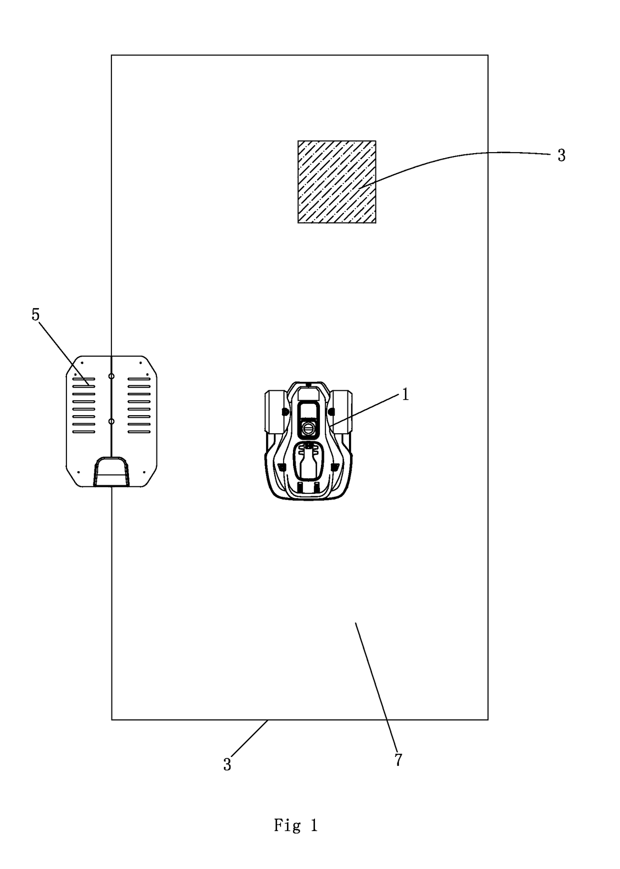
[0131]As shown in FIG. 1, the autonomous working system in the embodiment of the present invention comprises an autonomous vehicle 1, a limit 3 and a dock 5, wherein the limit 3 is used for limiting the working area 7 of the autonomous working system; the autonomous vehicle moves and works within or between the limit; and the dock is configured for supplying docking for the autonomous vehicle, in particular for supplying energy after the autonomous vehicle returns to supplement energy.

[0132]Limit is the common name of borders and obstacles. The border is the periphery of the whole working area, usually connected end to end to enclose the working area. The border may be a tangible body like a wall, fence, rail, etc., or electronically virtual signal border like an electromagnetic signal or optical signal sent by the a border signal generator. The obstacle ...


PUM


Abstract

Disclosed in the present invention is an autonomous vehicle (1), which comprises an housing (21), an driving module mounted on the housing (21), an borderline detecting module mounted on the housing for detecting the distance between the autonomous vehicle (1) and the borderline (3), an energy module mounted on the housing for providing energy for the autonomous vehicle, and an control module electrically connected with the driving module and the borderline detecting module. The control module controls the driving module to perform steering based on the signal representing the angle relationship between the autonomous vehicle (1) and the borderline (3) transmitted from the borderline detecting module, so that the axis (33) of the autonomous vehicle (1) always forms an acute angle or an right angle with one side of the borderline (3) while steering is completed, but another side of the borderline (3) forms an acute angle or an right angle with the core axis (33) of the autonomous vehicle (1) when the turning begins. The turning has directivity, so that the autonomous vehicle more easily goes out from the narrow area and the efficiency of area covering is higher; moving is kept during the turning, so that the energy is saved, and the working efficiency is improved.

Description

TECHNICAL FIELD[0001]The present invention relates to the field of smart control, in particular to an autonomous vehicle, an autonomous working system and a turning method for the autonomous vehicle.DESCRIPTION OF THE RELATED ART[0002]Along with the continuous development of the computer technology and artificial intelligence technology, autonomous working systems similar to the intelligent robots have slowly enter people's life. Sumsung, Electrolux, and other company have both developed fully autonomous dust collectors and put into the market. Those fully autonomous dust collectors are usually small and integrated with an environment sensor, a self-driving system, a dust collection system, a battery and a charging system, can autonomously cruise in the room without operation by people, return to the dock to be docked and charged when the power level is low, and then continue to cruise collector dust. Meanwhile, Husqvarna AB and other companies have developed the similar robot mower...

Claims


Application Information

Patent Timeline
Patent Type & Authority Patents(United States)
IPC IPC(8): G05D1/02A01D34/00
CPCG05D1/021A01D34/008G05D1/0265Y10S901/01G05D2201/0215
Inventor BORINATO, GIANNI
Owner POSITEC POWER TOOLS (SUZHOU) CO LTD
Why Eureka
Try Eureka