Fuel cell vehicle air-conditioning apparatus and control method thereof

a fuel cell and air-conditioning technology, which is applied in the direction of vehicle heating/cooling devices, electric devices, driver interactions, etc., can solve the problems of fuel cell temperature rising beyond the temperature at which the fuel cell can operate efficiently, and the power generation efficiency of the fuel cell may decrease, so as to suppress the deterioration of the fuel efficiency of the vehicle

Active Publication Date: 2018-06-05
TOYOTA JIDOSHA KK
View PDF11 Cites 9 Cited by
  • Summary
  • Abstract
  • Description
  • Claims
  • Application Information

AI Technical Summary

Benefits of technology

[0010]The invention provides a fuel cell vehicle air-conditioning apparatus and a control method thereof with which heating can be performed during a normal operation of the fuel cell vehicle while suppressing deterioration of a fuel efficiency of the vehicle.
[0013]According to the configurations described above, the fuel consumption amount can be reduced by calculating the optimum temperature, which is the temperature of the fuel cell at which the fuel consumption amount required for the fuel cell to generate the total power generation amount, i.e. the sum of the heating power generation amount and the travel power generation amount, reaches a minimum, and controlling the cooling system such that the temperature of the fuel cell reaches the optimum temperature, and as a result, deterioration of the vehicle fuel efficiency can be suppressed. Further, this control is executed not only when the vehicle performs an idling stop but also during a normal operation, and therefore heating can be performed in the fuel cell vehicle during a normal operation. As a result, heating can be performed in the fuel cell vehicle during a normal operation while suppressing deterioration of the vehicle fuel efficiency.
[0016]According to the configurations described above, when the temperature of the fuel cell is lower than the optimum temperature, the temperature of the fuel cell can be raised toward the optimum temperature by storing the waste heat of the fuel cell in the fuel cell. As a result, deterioration of the vehicle fuel efficiency can be suppressed more reliably.
[0017]The heat creation unit may increase an amount of heat discharged from the fuel cell by reducing a power generation efficiency of the fuel cell below that of a normal operation.

Problems solved by technology

In the related art described in JP-2004-146144 A, however, use of the waste heat stored in the fuel cell system for performing heating during a normal operation of a fuel cell vehicle is not envisaged.
Further, when surplus waste heat from the fuel cell is simply stored in the fuel cell system during a normal operation in the fuel cell vehicle, the temperature of the fuel cell rises beyond the temperature at which the fuel cell can operate efficiently.
As a result, a power generation efficiency of the fuel cell may decrease, leading to deterioration of a fuel efficiency of the vehicle.

Method used


Image

  • Fuel cell vehicle air-conditioning apparatus and control method thereof
  • Fuel cell vehicle air-conditioning apparatus and control method thereof
  • Fuel cell vehicle air-conditioning apparatus and control method thereof

Examples


Embodiment Construction

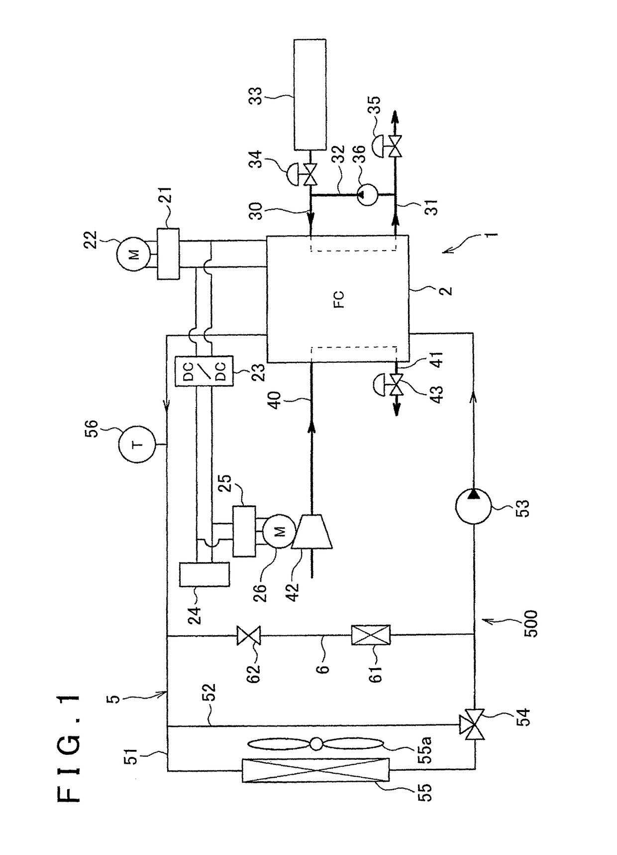
[0029]An embodiment of the invention will be described below on the basis of FIGS. 1 to 7. FIG. 1 is an overall configuration diagram showing a fuel cell vehicle air-conditioning apparatus according to this embodiment. A fuel cell vehicle air-conditioning apparatus 1 is applied to a so-called fuel cell vehicle, which is a type of electric vehicle.

[0030]As shown in FIG. 1, the fuel cell vehicle air-conditioning apparatus 1 includes a fuel cell 2 that generates power by an electrochemical reaction between air (an oxidant gas) and hydrogen (a fuel gas). The fuel cell 2 is formed with a stacked structure in which a plurality of single cells that generate power when supplied with air and hydrogen are stacked.

[0031]A part of the direct current power generated by the fuel cell 2 is converted into an alternating current by a first inverter 21 and supplied to various electric loads such as a vehicle travel electric motor 22. A further part of the direct current power generated by the fuel ce...


PUM

PropertyMeasurementUnit
temperatureaaaaaaaaaa

Abstract

A fuel cell vehicle air-conditioning apparatus includes: a cooling system that adjusts a temperature of a fuel cell; a waste heat collection unit that collects at least a part of waste heat from the fuel cell and uses the collected waste heat to heat a cabin interior of the fuel cell vehicle; and a heat creation unit that creates heat for heating the fuel cell vehicle. The fuel cell vehicle air-conditioning apparatus calculates a fuel consumption amount required for the fuel cell to generate a total power generation amount, which is a sum of a heating power generation amount and a travel power generation amount, calculates an optimum temperature, which is a temperature of the fuel cell at which the fuel consumption amount reaches a minimum, and controls the cooling system such that the temperature of the fuel cell reaches the optimum temperature.

Description

CROSS-REFERENCE TO RELATED APPLICATIONS[0001]This is a national phase application based on the PCT International Patent Application No. PCT / IB2012 / 002508 filed on Nov. 28, 2012, claiming priority to Japanese application No. 2011-266821 filed Dec. 6, 2011, the entire contents of both of which are incorporated herein by reference.BACKGROUND OF THE INVENTION[0002]1. Field of the Invention[0003]The invention relates to an air-conditioning apparatus applied to a fuel cell vehicle, and a control method thereof.[0004]2. Description of Related Art[0005]In a conventional air-conditioning apparatus for a fuel cell vehicle that includes a fuel cell as a traveling drive source, a heating effect is improved by supplying heat from high-temperature cooling water used to cool the fuel cell, or in other words waste heat from the fuel cell, to a heater core for heating a cabin interior.[0006]A conventional fuel cell vehicle air-conditioning apparatus of this type includes operating state detecting me...

Claims


Application Information

Patent Timeline
Patent Type & Authority Patents(United States)
IPC IPC(8): B60H1/00B60H1/22H01M8/04014B60H1/14B60H1/03H01M8/04858H01M8/04007H01M8/04029H01M8/04701H01M8/0432H01M8/04089B60L11/18B60L7/14B60L3/00B60L1/02B60L1/00H01M16/00H01M8/04746
CPCB60H1/034B60L1/003B60L1/02B60L3/0053B60L7/14B60L11/1803B60L11/1868B60L11/1887B60L11/1892B60L11/1894H01M8/04014H01M8/04029H01M8/0432H01M8/04052H01M8/0488H01M8/04358H01M8/04701H01M8/04746B60H1/143Y02T90/34B60H1/00385B60H2001/2228B60L2210/10B60L2240/34B60L2240/36B60L2240/662B60L2250/16H01M8/04089H01M16/006H01M2250/20H01M2250/405Y02B90/16Y02T10/7066Y02T10/7216Y02T10/7291Y02T90/16Y02T90/32B60L58/33B60L58/34B60L58/40B60L58/20B60L50/51Y02B90/10Y02T10/70Y02T10/72Y02T90/40Y02E60/50Y02E60/10F16D61/00B60T1/10
Inventor KOYAMA, TAKASHISAKAJO, YUICHISUEMATSU, KEIGO
Owner TOYOTA JIDOSHA KK
Why Eureka
Try Eureka