Catalytic converter

a catalytic converter and converter technology, applied in the field of catalytic converters, can solve the problems of engine emissions of harmful substances to the environment, marked decline, and lower catalytic activity, and achieve excellent nox conversion performance, excellent thermal shock resistance, and excellent osc.

Active Publication Date: 2018-06-19
TOYOTA JIDOSHA KK
View PDF23 Cites 14 Cited by
  • Summary
  • Abstract
  • Description
  • Claims
  • Application Information

AI Technical Summary

Benefits of technology

[0014]Accordingly, the invention provides a catalytic converter having an excellent OSC, an excellent NOx conversion performance under high engine load, and an excellent catalyst warm-up performance.
[0016]In the catalytic converter according to this aspect of the invention, a zone-coated catalyst is employed as the catalyst layer formed on the cell wall of the substrate having the cell structure. The bottom catalyst layer is provided on the surface of the substrate along the entire length of the substrate. The top catalyst layer is stacked on the surface of the bottom catalyst layer. Thus, the catalytic converter according to this aspect of the invention has catalyst layers constituting a two-layer structure. The first top catalyst layer is provided on the upstream side (Fr side) of the substrate in the exhaust gas flow direction, and the second top catalyst layer is provided on the downstream side (Rr side) of the substrate. That is, the zone-coated catalyst layer is employed as the top catalyst layer in catalyst layers constituting the two-layer structure. The first top catalyst layer has the support made of the ceria-free zirconia composite oxide, and the second top catalyst layer has the support made of the ceria-containing zirconia composite oxide. The first top catalyst layer and the second top catalyst layer both support Rh. The first top catalyst layer is formed over the range that is X % of the entire length of the substrate, where X is from 30 to 70. In addition, the ratio SD1 / SD2 of the density of supported Rh (SD1) in the first top catalyst layer to the density of supported Rh (SD2) in the second top catalyst layer is at least 1 and at most 3. This arrangement provides a catalytic converter which has an excellent OSC, an excellent NOx conversion performance under high engine load, and also an excellent catalyst warm-up performance.
[0022]The catalytic converter according to this aspect of the invention may preferably have a cordierite honeycomb support with an excellent thermal shock resistance. Alternatively, the catalytic converter of this aspect of the invention may be an electrically heated catalytic converter (available as an electrically heated converter (EHC)). The electrically heated catalytic converter is constructed so as to heat the honeycomb catalyst by, for example, attaching a pair of electrodes to a honeycomb catalyst and passing electricity through the electrodes. The activity of the honeycomb catalyst is increased in this way, thereby rendering harmless the exhaust gas passing through the catalytic converter. By employing an electrically heated catalytic converter in the exhaust system that connects the vehicle engine and the muffler, in addition to purifying exhaust gases at ordinary temperatures, exhaust gases can be purified even at cold temperatures because the catalyst is activated by electrical heating.
[0023]As can be appreciated from the above explanation, the catalytic converter provided according to this aspect of the invention has an excellent OSC, an excellent NOx conversion performance during high engine load, and also has an excellent catalyst warm-up performance.

Problems solved by technology

The engine may emit harmful substances to the environment, such as carbon monoxide (CO) and NOx, unburned hydrocarbons (HCs) and volatile organic compounds (VOCs).
However, greatly decreasing the amount of noble metal catalysts in three-way catalysts also greatly lowers the catalytic activity, resulting in marked declines in, for example, the OSC, the low-temperature activity, and also the NOx conversion performance in a high-temperature environment.
This is because a large decrease in the amount of noble metal catalysts greatly lowers the number of active sites, and the greatly lowered number of catalyst reaction sites leads to a pronounced decline in the conversion performance.
However, there is also a trade-off in that increasing the amount of cerium oxide in the support has the undesired effect of lowering the NOx conversion performance distinctive to Rh.

Method used


Image

  • Catalytic converter
  • Catalytic converter
  • Catalytic converter

Examples


embodiment

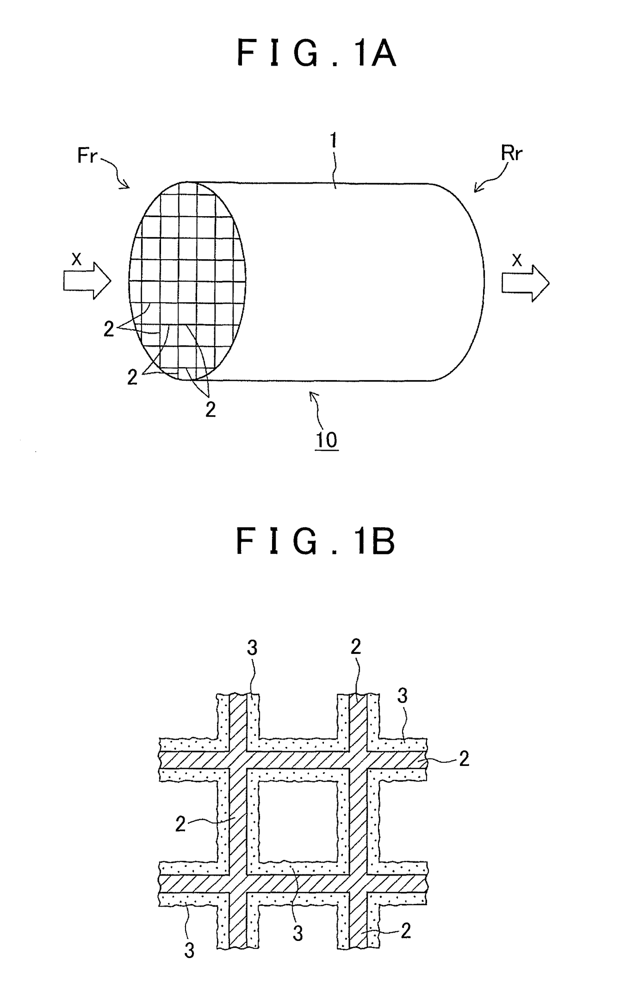
[0033](Embodiment of Catalytic Converter)

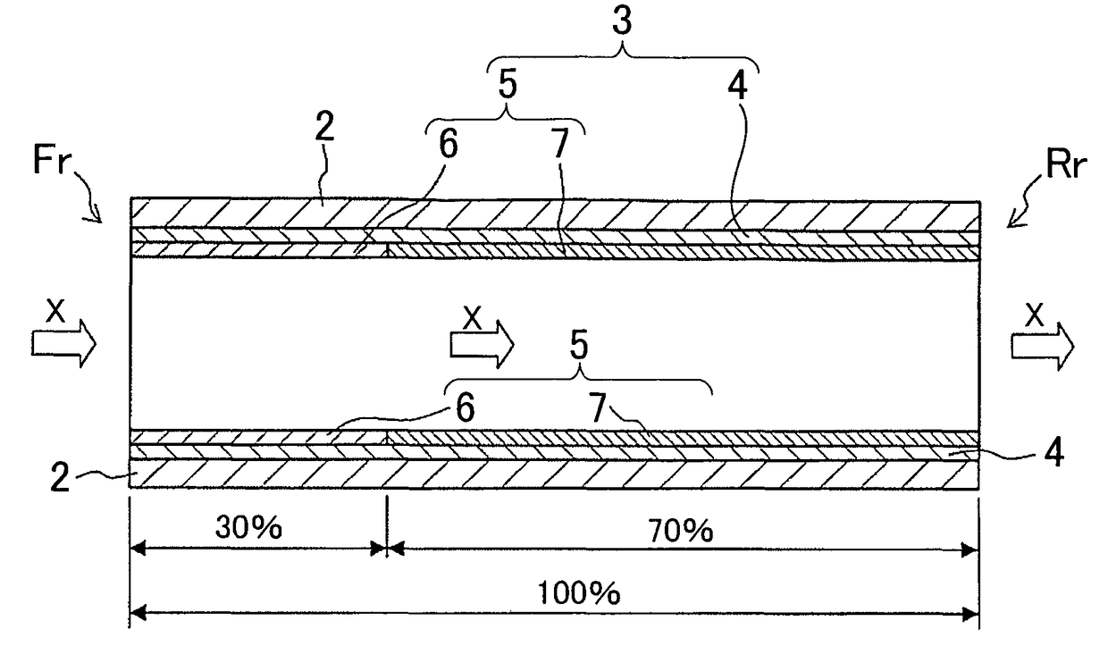
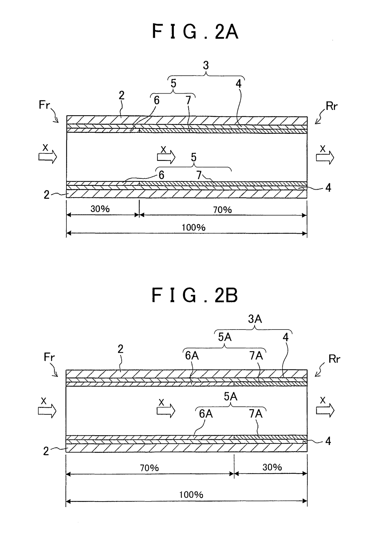
[0034]FIG. 1A is a schematic view of a catalytic converter according to an embodiment of the invention, and FIG. 1B is an enlarged view of some of the cells in the catalytic converter. FIGS. 2A and 2B are longitudinal sectional views showing embodiments of the catalyst layer in the catalytic converter.

[0035]The catalytic converter 10 shown in FIGS. 1A and 1B is formed of a tubular substrate 1 having numerous cells and a catalyst layer 3 formed on the surfaces of cell walls 2 making up the cells. The cell structure may be regarded as being constituted by the numerous cells.

[0036]Here, the material making up the substrate 1 is exemplified by ceramic materials such as cordierite (made of a composite oxide of magnesium oxide, aluminum oxide and silicon dioxide) and silicon carbide, and materials other than ceramic materials, such as metallic materials.

[0037]The substrate 1 has a honeycomb structure constituted by numerous lattices, e.g., tetragon...


PUM

PropertyMeasurementUnit
concentrationaaaaaaaaaa
temperatureaaaaaaaaaa
lengthaaaaaaaaaa

Abstract

A catalytic converter includes a substrate (1) and a catalyst layer (3). The catalyst layer includes a bottom catalyst layer (4), a first top catalyst layer (6) and a second top catalyst layer (7). The second top catalyst layer is provided on a downstream side relative to the first top catalyst layer. The first top catalyst layer is made of a ceria-free zirconia composite oxide support and rhodium. The second top catalyst layer is made of a ceria-containing zirconia composite oxide support and rhodium. The first top catalyst layer has a length that is X % of the entire length of the substrate. The second top catalyst layer has a length that is 100−X % of the entire length of the substrate. A ratio of a density of rhodium in the first top catalyst layer to a density of rhodium in the second top catalyst layer is at least 1 and at most 3.

Description

BACKGROUND OF THE INVENTION[0001]1. Field of the Invention[0002]The invention relates to a catalytic converter that is housed within a pipe making up an exhaust gas emission system and is secured to the pipe.[0003]2. Description of Related Art[0004]A variety of efforts aimed at reducing environmental impacts and burden are being carried out on a global scale in many industrial fields. In the automotive industry, developments are constantly being made to expand the use and further enhance the performance of not only high fuel-performance gasoline engine vehicles, but also “eco cars” such as hybrid vehicles and electric cars. In addition to the development of such eco cars, active research is also being conducted on exhaust gas purifying catalysts which purify the exhaust gases emitted by engines. Such exhaust gas purifying catalysts include oxidation catalysts, three-way catalysts and nitrogen oxide (NOx) storage / reduction catalysts. In such exhaust gas purifying catalysts, the catal...

Claims


Application Information

Patent Timeline
Patent Type & Authority Patents(United States)
IPC IPC(8): B01J23/10B01J23/00B01J23/46B01J35/00B01J23/63B01D53/94B01J37/02B01J23/44B01J35/04F01N3/10
CPCB01J23/464B01D53/945B01J23/10B01J23/44B01J23/63B01J35/0006B01J35/04B01J37/0244B01J37/0248B01D2255/1023B01D2255/1025B01D2255/2065B01D2255/20715B01D2255/40B01D2255/407B01D2255/908B01D2255/9022B01D2255/9032B01D2255/9155B01D2258/014B01J2523/00F01N3/101F01N2510/0684Y02T10/22B01J2523/25B01J2523/31B01J2523/36B01J2523/3706B01J2523/3712B01J2523/3725B01J2523/48B01J2523/822B01J2523/824Y02T10/12
Inventor AOKI, YUKI
Owner TOYOTA JIDOSHA KK
Why Eureka
Try Eureka