
Surface-acoustic-wave filters with poles of attenuation created by impedance circuits

a technology of impedance circuit and surface acoustic wave, which is applied in the direction of multiple-port network, electrical apparatus, and electromechanical/electrostrictive/magnetostrictive devices, etc., can solve the problems of difficult to meet the above requirements satisfactorily with a saw ladder filter, difficult to provide wide stopbands with the necessary high attenuation, and difficult to solve. , to achieve the effect of improving the frequency characteristic of the filter, increasing the stopband

Inactive Publication Date: 2002-04-09
HANGER SOLUTIONS LLC
View PDF12 Cites 25 Cited by
  • Summary
  • Abstract
  • Description
  • Claims
  • Application Information

AI Technical Summary

Benefits of technology

A general object of the present invention is to improve the frequency characteristics of SAW ladder filters having poles.
A further object is to obtain steep roll-off between the passband and stopband.
In both aspects of the invention, the pole of attenuation created by the impedance circuit improves the frequency characteristic of the filter by increasing the stopband attenuation, enabling a high attenuation to be obtained over a wide range of stopband frequencies, with steep roll-off between the passband and stopband.

Problems solved by technology

As increasing performance demands are placed on mobile communications equipment, however, it is becoming difficult to meet the above requirements satisfactorily with a SAW ladder filter.
Providing wide stopbands with the necessary high attenuation is particularly difficult.
These problems are difficult to solve by using the relationships between the passband and stopbands and the resonant frequencies (series resonance frequencies) and antiresonant frequencies (parallel resonance frequencies) of the SAW resonators in a SAW ladder filter, because of restrictions on the width, placement, and spacing of the passband and stopbands.
It is particularly difficult to place wide stopbands with high attenuation close to the passband and still maintain a low insertion loss in the passband.

Method used


Image

  • Surface-acoustic-wave filters with poles of attenuation created by impedance circuits
  • Surface-acoustic-wave filters with poles of attenuation created by impedance circuits
  • Surface-acoustic-wave filters with poles of attenuation created by impedance circuits

Examples


first embodiment

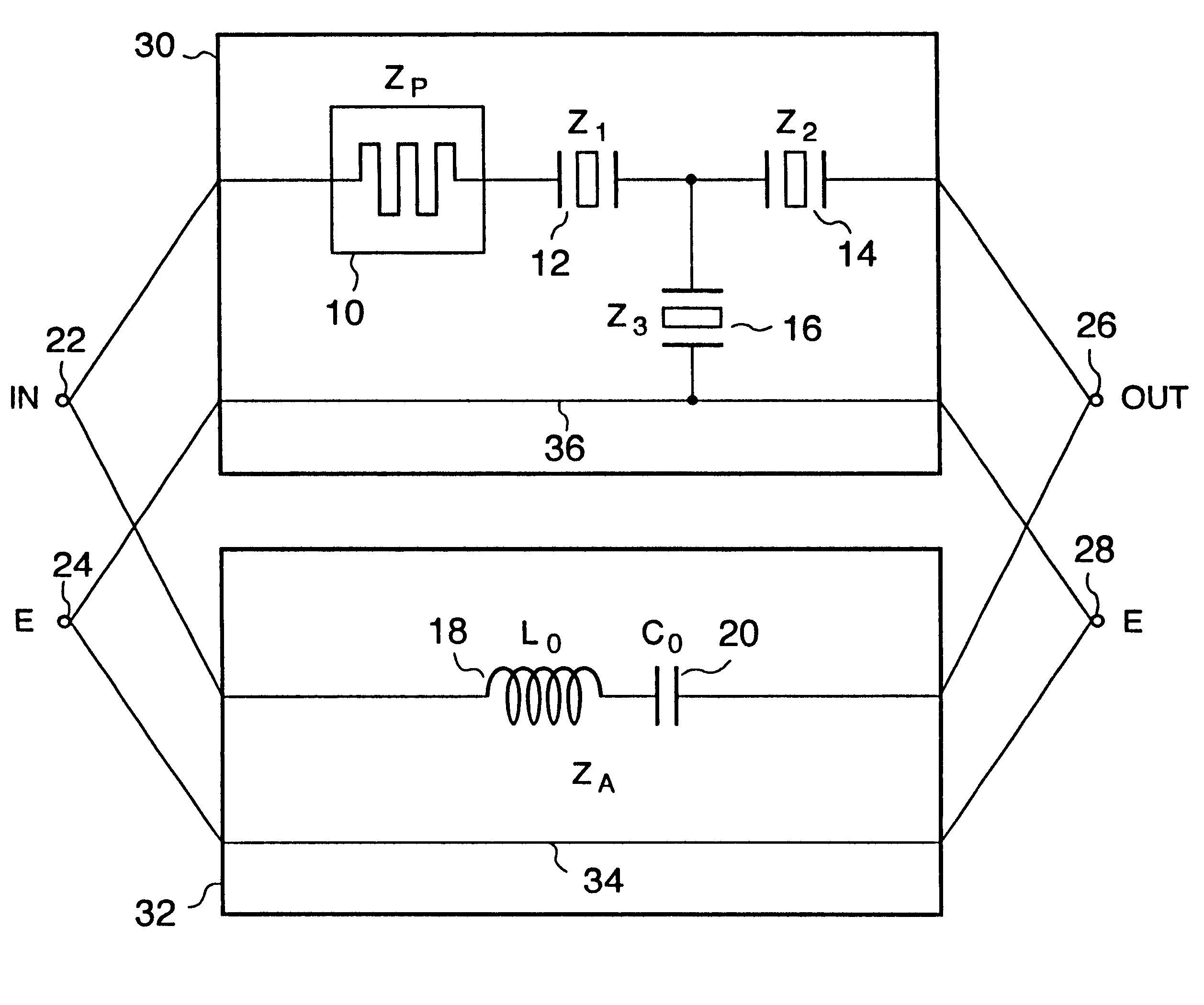
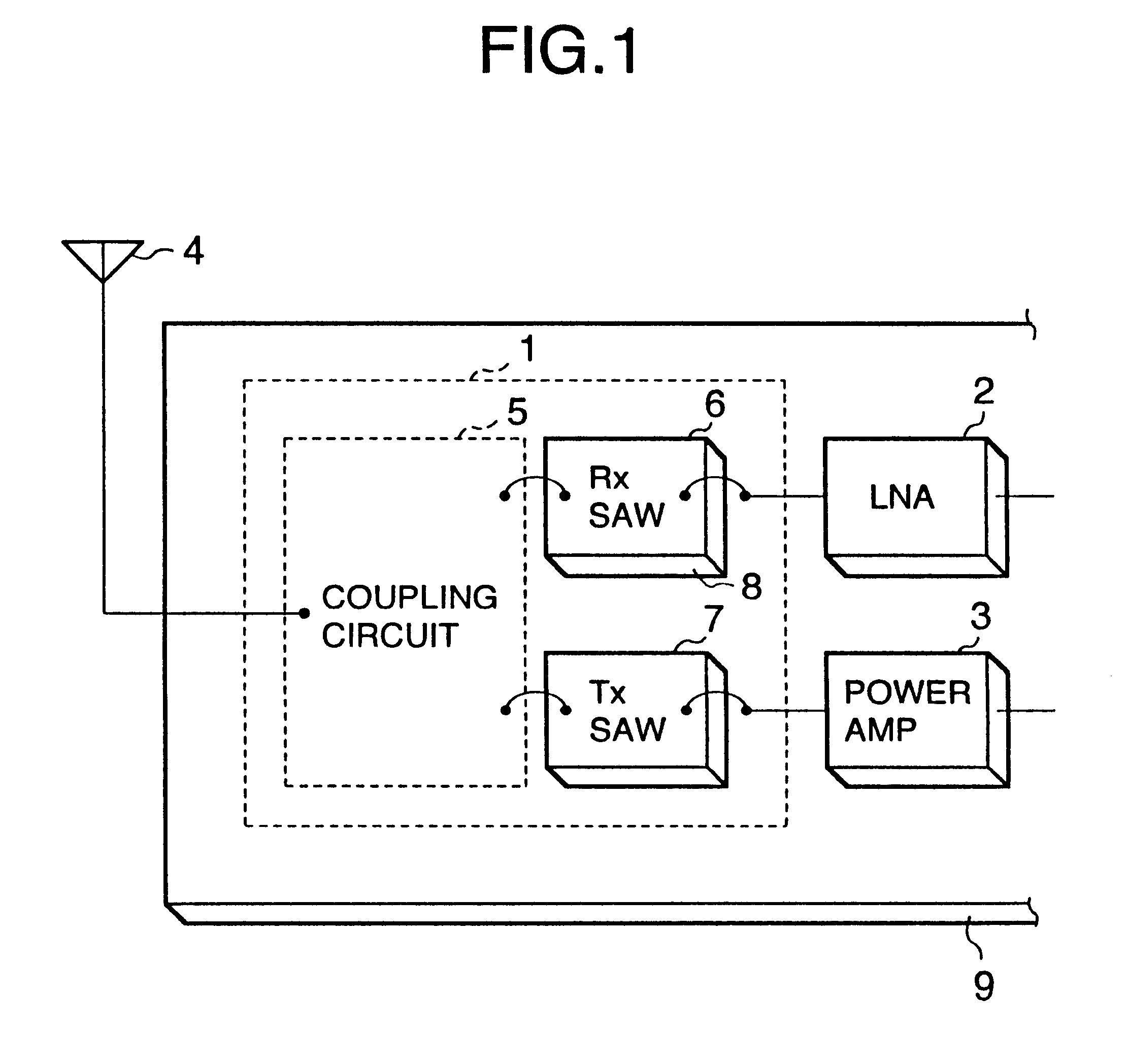
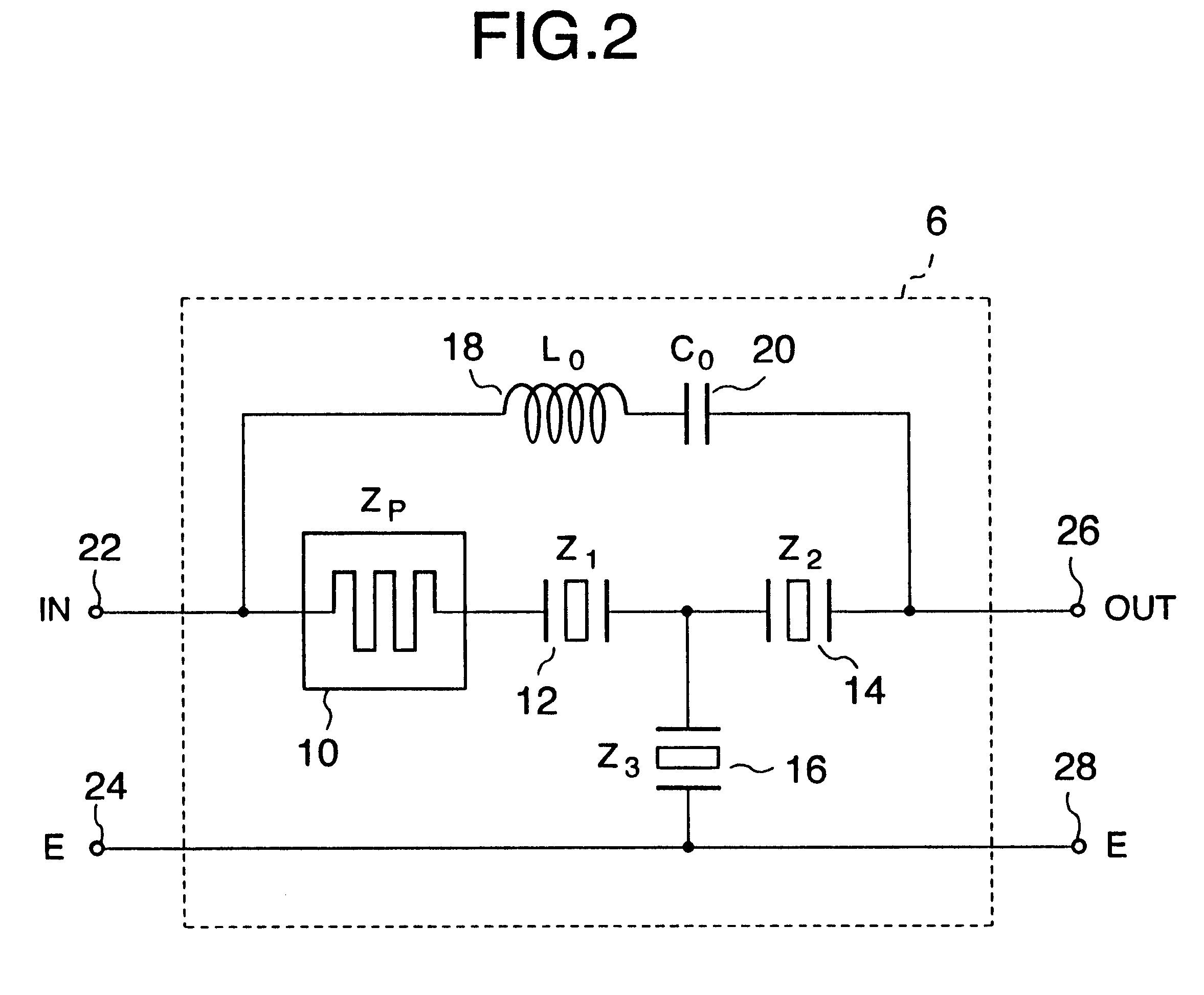
The first embodiment of the invention is a SAW filter suitable for use as the receiving filter 6 in FIG. 1. Referring to FIG. 2, this embodiment of the receiving filter 6 comprises a phase shifter 10, a pair of series-arm SAW resonators 12 and 14, a shunt-arm SAW resonator 16, an inductor 18, and a capacitor 20. These elements form a two-port circuit, the input port comprising an input terminal 22 and ground or earth (E) terminal 24, and the output port comprising an output terminal 26 and ground terminal 28.

The phase shifter 10 and series-arm SAW resonators 12 and 14 are coupled in series between the input terminal 22 and output terminal 26. The inductor 18 and capacitor 20 are also coupled in series between the input terminal 22 and output terminal 26, in parallel with the phase shifter 10 and series-arm SAW resonators 12 and 14. The shunt-arm SAW resonator 16 is coupled, on one side, to a node disposed between the two series-arm SAW resonators 12 and 14, and on the other side to ...

second embodiment

To improve the stopband attenuation characteristics, further SAW resonators can be added as shown in FIG. 7. As in the first embodiment, the impedance circuit comprises an inductor 18 with an impedance L.sub.O of 3.0 nH, and a capacitor 20 with a capacitance C.sub.O of 0.1 pF. The phase shifter 10 is again an 11-cm stripline. Each of the series-arm SAW resonators 12, 14, and 38 comprises an interdigital transducer with one hundred pairs of electrode fingers and an aperture of 50 .mu.m. As in the first embodiment, the inductor 18 and capacitor 20 are coupled in parallel with the phase shifter 10 and the first pair of series-arm SAW resonators 12 and 14.

The second embodiment has four shunt-arm SAW resonators 40, 42, 44, and 46, which are coupled in a ladder configuration with the series-arm SAW resonators. The first and last shunt-arm SAW resonators 40 and 46 each have an interdigital transducer with sixty pairs of electrode fingers and an aperture of 60 .mu.m. The two inner shunt-arm...

third embodiment

The third embodiment is designed so that this condition is satisfied over a wide range of high frequencies, as will be illustrated below.

For comparison, FIG. 15 shows a conventional SAW filter lacking the inductor 58 of the third embodiment. FIG. 16 shows the corresponding equivalent lumped-constant circuit representation. The circuit constants in FIG. 16 are the same as the corresponding constants in FIG. 13.

Graphs of the open-circuited impedance Z.sub.O and short-circuited impedance Z.sub.S of this conventional SAW filter are shown in FIG. 17. The horizontal axis indicates frequency in hertz (Hz); the vertical axis indicates impedance in ohms (.OMEGA.). Z.sub.O and Z.sub.S were calculated from equations (7) to (11) with L.sub.O set equal to zero. The difference between Z.sub.O and Z.sub.S in the frequencies above about 875 MHz should be noted, as these frequencies are located in the desired upper stopband of the filter.

FIG. 18 shows the open-circuited impedance Z.sub.O and short-c...


PUM


Abstract

A surface-acoustic-wave filter couples a two-port surface-acoustic-wave resonator filter circuit coupled in parallel or in series with a two-port impedance circuit. The two-port impedance circuit has an impedance that creates a pole of attenuation, by making the open-circuit impedance of the surface-acoustic-wave filter equal to the short-circuit impedance. High attenuation over a wide range of stopband frequencies is obtained in this way, combined with steep roll-off between the passband and stopband.

Description

BACKGROUND OF THE INVENTIONThe present invention relates generally to surface-acoustic-wave filters having poles, and more particularly to surface-acoustic-wave filters of the resonator type used, for example, in mobile communications equipment.Like integrated circuits, surface-acoustic-wave filters, referred to below as SAW filters, and lightweight, and can easily be mass-produced. For these reasons, SAW filters are widely used as radio-frequency (RF) filters in devices such as portable telephone sets and pagers.A portable telephone set of the code division multiple access (CDMA) type, for example, transmits in one frequency band and receives in an adjacent frequency band. The set accordingly requires an antenna duplexer with a pair of filters, one filter passing frequencies in the transmitting band and rejecting frequencies in the receiving band, while the other filter performs the opposite function. Each filter which must provide low passband insertion loss, steep roll-off betwee...

Claims


Application Information

Patent Timeline
IPC IPC(8): H03H9/00H03H9/05H03H9/64H03H7/01H03H7/38H03H9/72
CPCH03H7/0115H03H7/1708H03H7/1725H03H7/175H03H7/1758H03H7/1766H03H7/1775H03H7/1783H03H7/1791H03H7/38H03H9/0576H03H9/6483H03H9/72H03H9/725H03H9/25H03H9/64H03H9/14541H03H9/42
Inventor EHARA, HISANORINOGUCHI, KAZUSHIGESHIMAMURA, HAJIMEOKADA, YOSHIOKOMAZAKI, TOMOKAZU
Owner HANGER SOLUTIONS LLC
Learn More