Polishing apparatus and method

abrasive grains, which is applied in the direction of abrasive surface conditioning devices, lapping machines, manufacturing tools, etc., can solve the problems of clogging the abrasive grains, failing to clean failing to achieve uniform cleaning of the entire surface of the abrasive cloth, so as to achieve the effect of effectively removing the abrasive grains and reliabl abrasive cloth, a technology of abrasive cloth, a technology of abrasive cloth, a technology of abrasive cloth, a technology of abrasive cloth, abrasive cloth, abrasive cloth, abrasive cloth, abrasive grain abrasive cloth, applied in the field of polishing apparatus and method, achieve the effect of abrasive cloth grain, abrasive cloth

Inactive Publication Date: 2003-08-19
EBARA CORP
View PDF26 Cites 13 Cited by
  • Summary
  • Abstract
  • Description
  • Claims
  • Application Information

AI Technical Summary

Benefits of technology

It is therefore an object of the present invention to provide a polishing apparatus which as a dressing device capable of uniformly cleaning the entire surface of an abrasive cloth and effectively removing abrasive grains from the abrasive cloth thereby to reliably prepare the abrasive cloth in readiness for reuse.

Problems solved by technology

As the polishing process progresses, the abrasive cloth is clogged with abrasive grains contained in the abrasive material.
The conventional dressing device is however disadvantageous in that it fails to clean the entire surface of the abrasive cloth 34 uniformly and cannot fully remove the abrasive grains which have embedded in the abrasive cloth This is because, as shown in FIG. 9(a), the abrasive cloth 34 is swept only in one direction depending on the rotational direction of the turntable 33, and hence the abrasive grains are removed from the abrasive cloth 34 only in one direction.
The dressing device shown in FIGS. 8(a) and 8(b) has a similar problem inn that it fails to achieve uniform cleaning of the entire surface of the abrasive cloth 34 and full removal of the abrasive grains which have stuck to the abrasive cloth 34.

Method used


Image

  • Polishing apparatus and method
  • Polishing apparatus and method
  • Polishing apparatus and method

Examples


Embodiment Construction

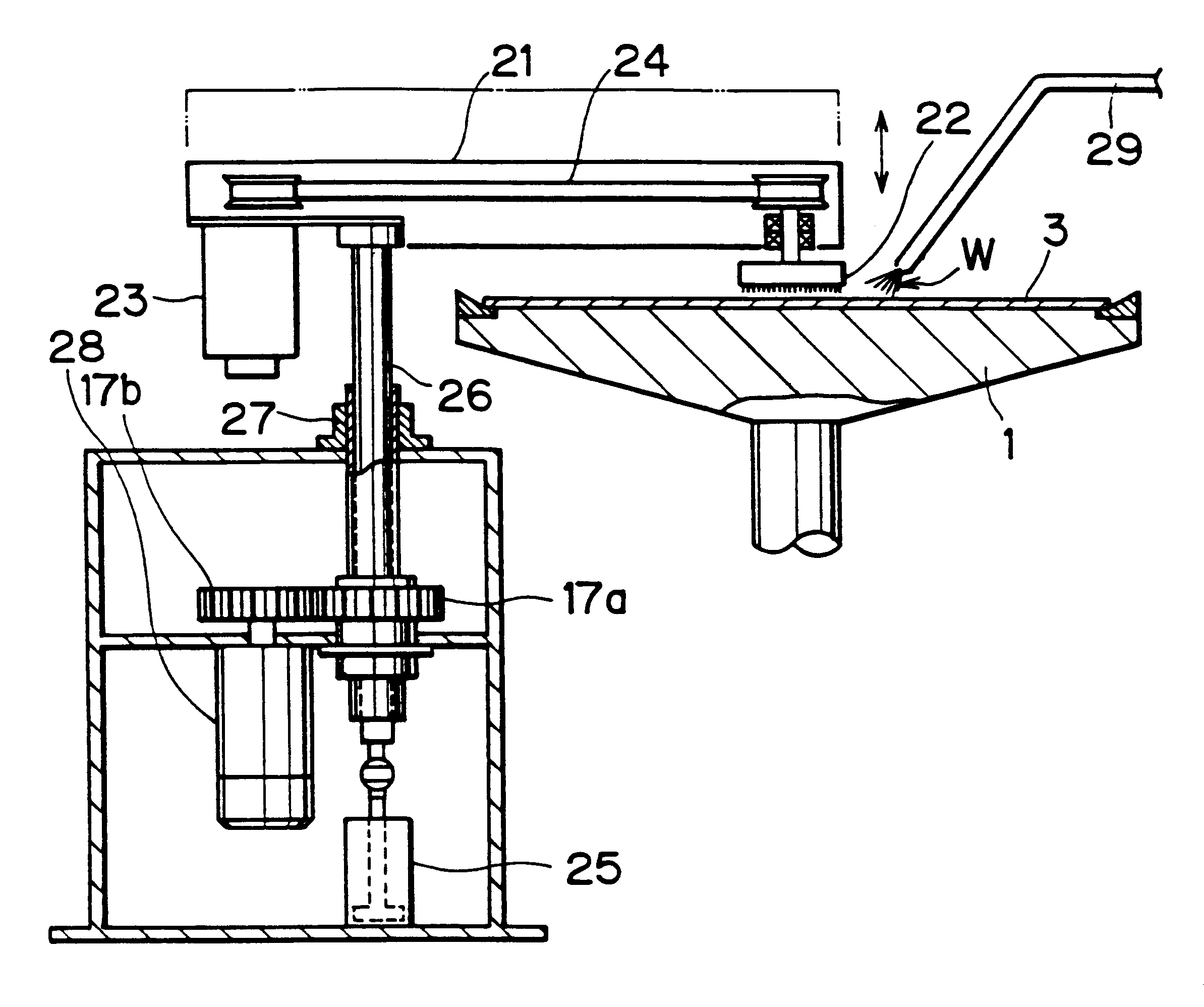
As shown in FIG. 1, a polishing apparatus according to the present invention comprises a turntable 1 mounted on the upper end of a shaft 2 which is rotatable about its own axis by a motor (not shown) coupled to the shaft 2. An abrasive cloth 3 is attached to the upper surface of the turntable 1. The polishing apparatus also has a top ring 4 disposed above the turntable 1 and coupled by a top ring holder 7 to the lower end of a vertical top ring drive shaft 6 through a spherical bearing 5. The top ring drive shaft 6 has a piston on its upper end which is slidably disposed in a vertical pressure cylinder 8. The pressure cylinder 8 is supplied with a fluid medium under pressure to lower the top ring drive shaft 6, and thereby pressing the top ring 4 against the turntable 1 under a constant pressure. The top ring drive shaft 6 is rotatable about its own axis by a train of gears 10a, 10b, 10c which are rotatable by a motor 9. The gear 10a is coaxially mounted on the top ring drive shaft ...


PUM

PropertyMeasurementUnit
distanceaaaaaaaaaa
abrasiveaaaaaaaaaa
distanceaaaaaaaaaa

Abstract

A turntable with an abrasive cloth mounted thereon and a top ring positioned above the turntable are independently rotatably provided. The top ring holds a workpiece to be polished and presses the workpiece against the abrasive cloth. The turntable and the top ring are rotated to polish the surface of the workpiece to a flat mirror finish on the abrasive cloth. A rotatable brush pressed against the abrasive cloth is rotated about an axis substantially perpendicularly to the plane of the abrasive cloth, and oscillated substantially radially between radially inner and outer positions over the abrasive cloth. A cleaning solution is sprayed from a nozzle onto the abrasive cloth. The turntable has a bank along an outer circumferential edge thereof for preventing a protective solution, which is supplied to the abrasive cloth to keep the abrasive cloth wet and prevent it, from flowing off the turntable when the turntable is stationary.

Description

BACKGROUND OF THE INVENTION1. Field of the InventionThe present invention relates to a polishing apparatus in general and more particularly to a polishing apparatus for polishing a workpiece such as a semiconductor wafer to a flat mirror finish with an abrasive cloth.2. Description of the Related ArtRecent rapid progress in semiconductor device integration demands smaller and smaller wiring patterns or interconnections and also narrower spaces between interconnections which connect active areas. One of the processes available for forming such interconnection is photolithography. Though the photolithographic process can form interconnections that are at most 0.5 .mu.m wide, it requires that surfaces on which pattern images are to be focused on by a stepper be as flat as possible because the depth of focus of the optical system is relatively small.It is therefore necessary to make the surfaces of semiconductor wafers flat for photolithography. One customary way of flattening the surfa...

Claims


Application Information

Patent Timeline
Patent Type & Authority Patents(United States)
IPC IPC(8): B24B53/007B24B37/04B24B37/26B24B53/017
CPCB24B37/26B24B53/017H01L21/321
Inventor HIROSE, MASAYOSHIISHIKAWA, SEIJIKIMURA, NORIOKAWASHIMA, KIYOTAKAISHII, YOU
Owner EBARA CORP
Why Eureka
Try Eureka