Ultraviolet detector

a detector and ultra-violet technology, applied in the field of ultra-violet detectors, can solve the problems of lowering the breakdown voltage, affecting and affecting the accuracy of the detector, so as to achieve the effect of reducing the stability and reliability of the detector and increasing the sensitivity

Inactive Publication Date: 2003-08-26
HAMAMATSU PHOTONICS KK
View PDF9 Cites 21 Cited by
  • Summary
  • Abstract
  • Description
  • Claims
  • Application Information

AI Technical Summary

Benefits of technology

In order to overcome such shortcomings, various studies have conventionally been made. The inventors have elucidated that these shortcomings result from the glass material used as a window material for the ultraviolet detector. Typical glass materials which are transparent to ultraviolet radiation contain fluorine. Upon welding of the envelope and bottom plate of the ultraviolet detector, fluorine contained in the glass material evaporated from the glass material and adsorbed onto the surfaces of the anode and cathode, the inner surface of the sealed vessel, and the like. Normal operation of the detector and the aging process in fabrication both include the gas discharge between the electrodes. Electrons and ions generated by the ...

Problems solved by technology

This alternation commonly results in the lowering of the breakdown voltage and that leads to occasional and continuous false dis...

Method used


Image

  • Ultraviolet detector
  • Ultraviolet detector
  • Ultraviolet detector

Examples


first embodiment

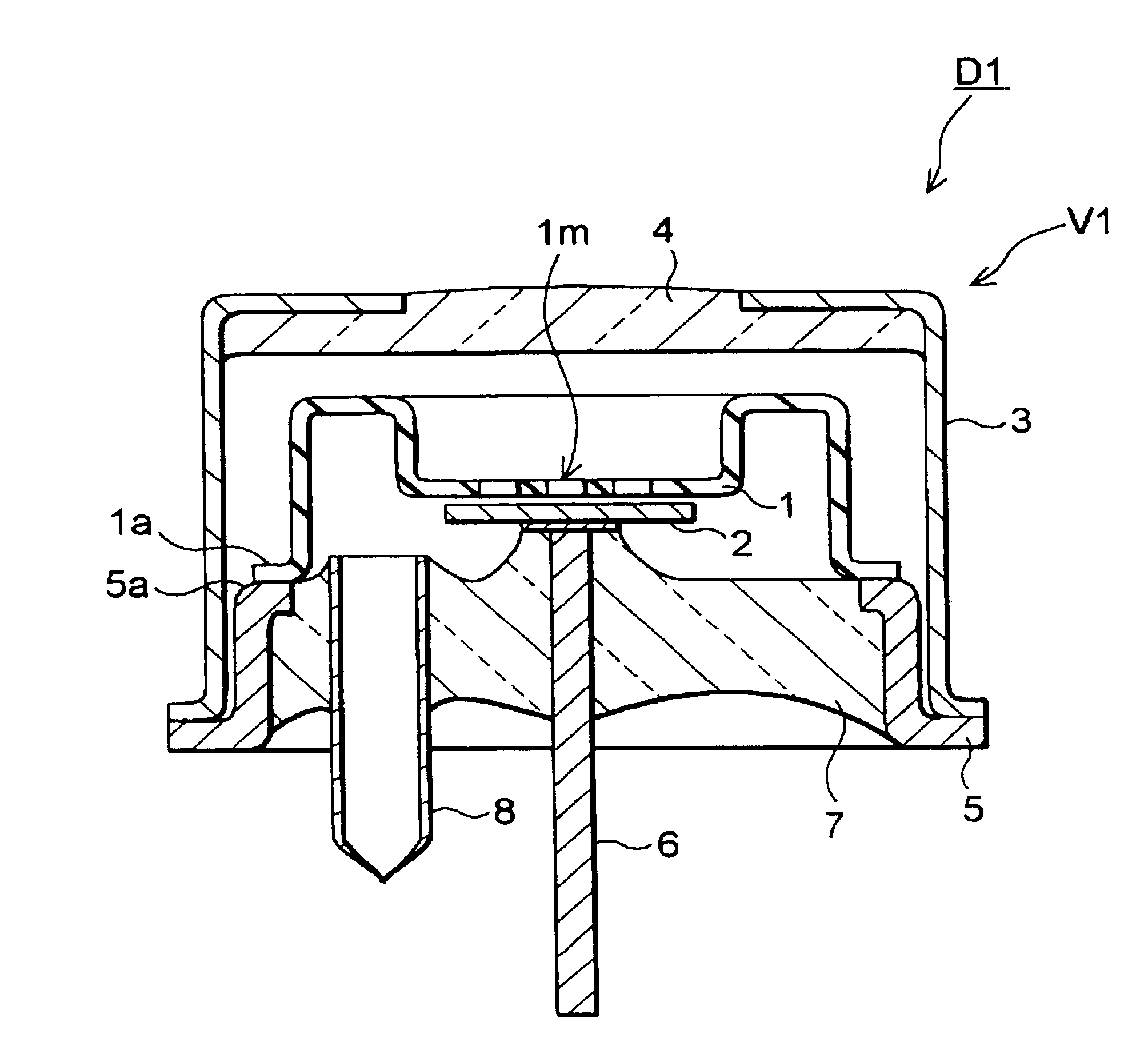
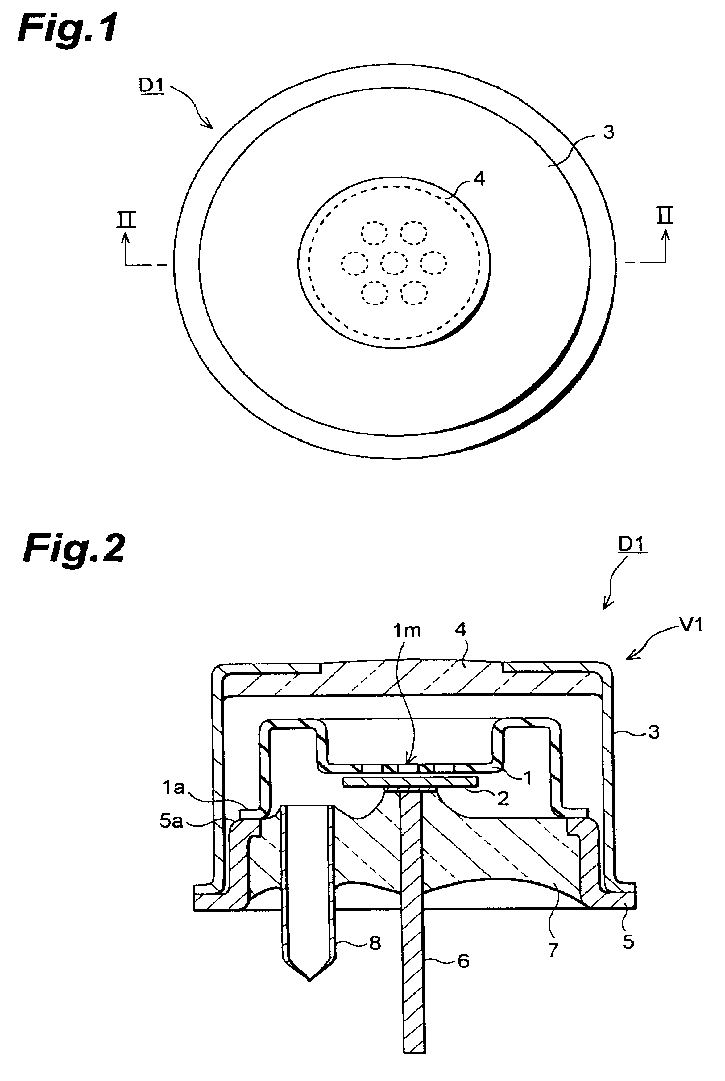
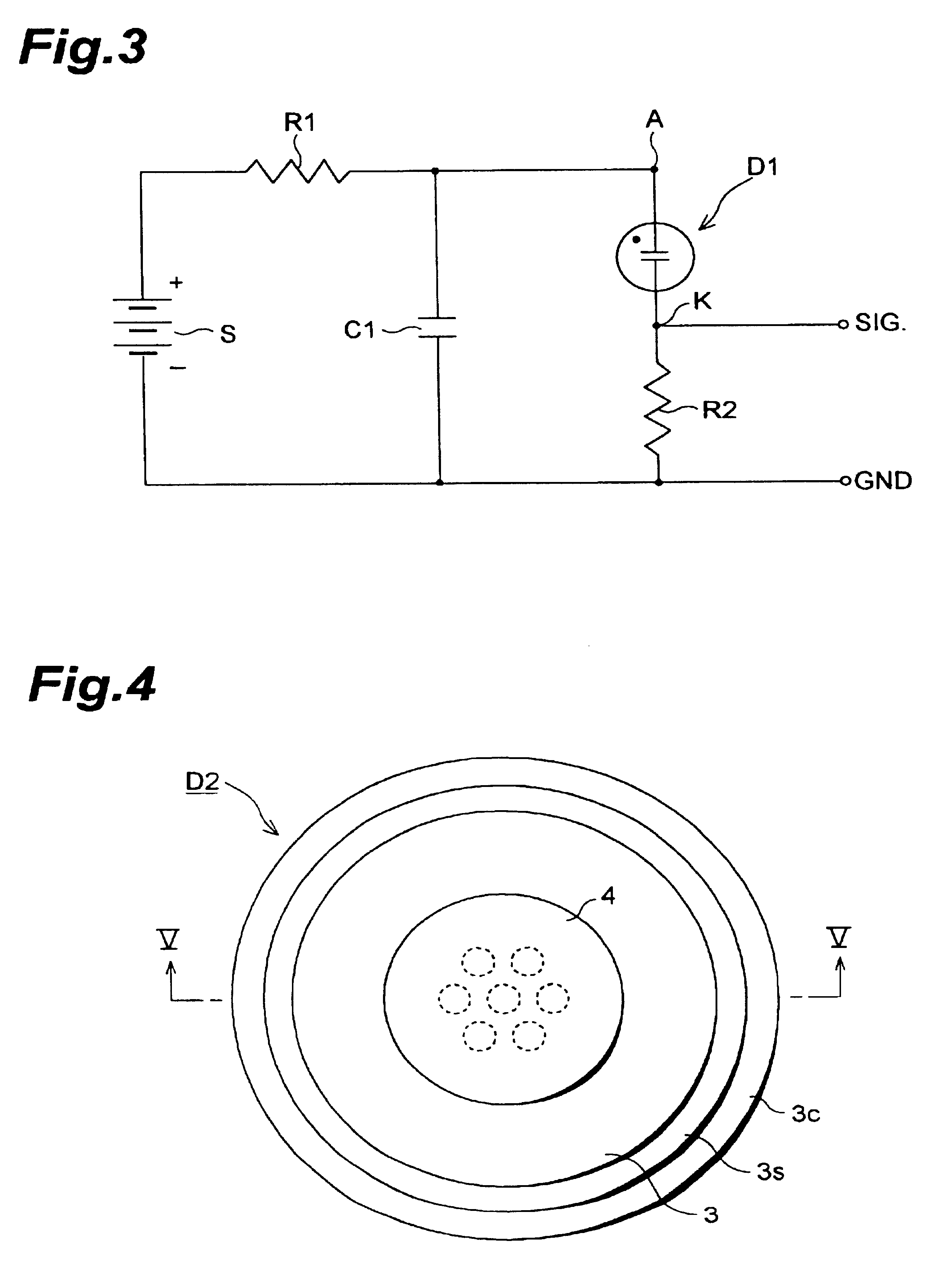
FIG. 1 is a plan view of an ultraviolet detector D1 in accordance with the present invention. FIG. 2 is a sectional view of the ultraviolet detector D1 taken along line II--II of FIG. 1. This detector comprises a sealed vessel V1, and an anode 1 and a cathode 2 which are disposed within the sealed vessel V1.

The sealed vessel V1 comprises a tubular member 3, made of a metal material blocking ultraviolet radiation, having two openings; a window member 4, made of an ultraviolet-transparent glass material, closing one of the openings of the tubular member 3; a ring-shaped metal member 5 secured to the tubular member 3 so as to close the other opening of the tubular member 3; and a glass sealant 7 sealing the opening in the ring-shaped metal member 5. The lower side wall portions of the tubular member 3 and ring-shaped metal member 5 are curved so as to project outward, and their curved portions are electrically welded together so as to overlap each other. The middle side wall portion of...

second embodiment

In the following, an ultraviolet detector D2 in accordance with the present invention will be explained. FIG. 4 is a plan view showing the ultraviolet detector D2. FIG. 5 is a sectional view of the ultraviolet detector D2 taken along line V--V of FIG. 4. This detector differs from that shown in FIGS. 1 and 2 only in the configurations of the upper part of the tubular member 3 and the anode 1. The diameter of the tubular member 3 differs between the upper part and lower part of the outer wall in its axial direction. Namely, the upper part of the outer wall has a diameter smaller than that of the lower part thereof, whereby their inner faces form a step 3s at the boundary therebetween. The step 3s of the inner face of the tubular member 3 has a lower surface 3b in parallel with the window member 4. Welded to the lower surface 3b of the step 3s is the upper surface of the outer edge of the planar anode 1. The distance between the upper surface 3c of the flange at the lower end of the r...


PUM


Abstract

An ultraviolet detector comprises a metal tubular member which hermetically encloses an anode and a cathode therein and is filled with a discharged gas introduced therein from a metal exhaust tube. After the anode and the cathode are enclosed within the tubular member, the ultraviolet detector can be made without being subjected to any glass fusing process. Accordingly, the inside of the sealed vessel V1 can be prevented from being contaminated with fluorine, whereby the ultraviolet detector with stable characteristics can be provided.

Description

BACKGROUND OF THE INVENTION1. Field of the InventionThe present invention relates to an ultraviolet detector which detects ultraviolet radiation incident thereon by converting them into an electric signal.2. Related Background ArtAn example of conventional ultraviolet detectors is disclosed in Japanese Utility model Publication No. 49-17184. This publication discloses an ultraviolet detector in which an anode and a cathode are disposed within a sealed vessel constituted by a glass envelope and a glass bottom plate welded to the bottom portion of the glass envelope.Though the conventional ultraviolet detector mentioned above is an excellent detector which has a long life and can stably detect ultraviolet radiation, its characteristics may not be sufficient. Specifically, when used for a long period of time, its characteristics may deteriorate over time, thus lacking in stability.SUMMARY OF THE INVENTIONIn order to overcome such shortcomings, various studies have conventionally been m...

Claims


Application Information

Patent Timeline
IPC IPC(8): H01J47/02H01J47/00
CPCH01J47/02G01J1/429G01J1/44G01J2001/4453
Inventor WARASHINA, HIDENAGASHIMAZU, YUJI
Owner HAMAMATSU PHOTONICS KK
Why Eureka
Try Eureka